I am an Electrical Engineering student at Olin College of Engineering with a focused passion for electric vehicles, battery technology, and power electronics. I combine my academic pursuits with extensive hands-on experience. My practical skills have been honed through numerous personal DIY projects, running my own business, and designing and manufacturing custom printed circuit boards for the Olin Electric Motorsports (FSAE) team, where I am now the project manager. I’m originally from Washington, DC, and plan to graduate Olin in 2028.
Personal Projects
Projects financed by me on my own time.
Off-Road Super Bike
An electric off-road motorcycle designed for ultimate performance.
City Ripper
A lightweight electric commuter that puts gas bikes to shame.
Mom-Mobile
An ATV for my mom, who gave me my love of speed.
Blueberry
The bike that started it all.
Off-Road Super Bike
An electric off-road motorcycle designed for ultimate performance.
Overview
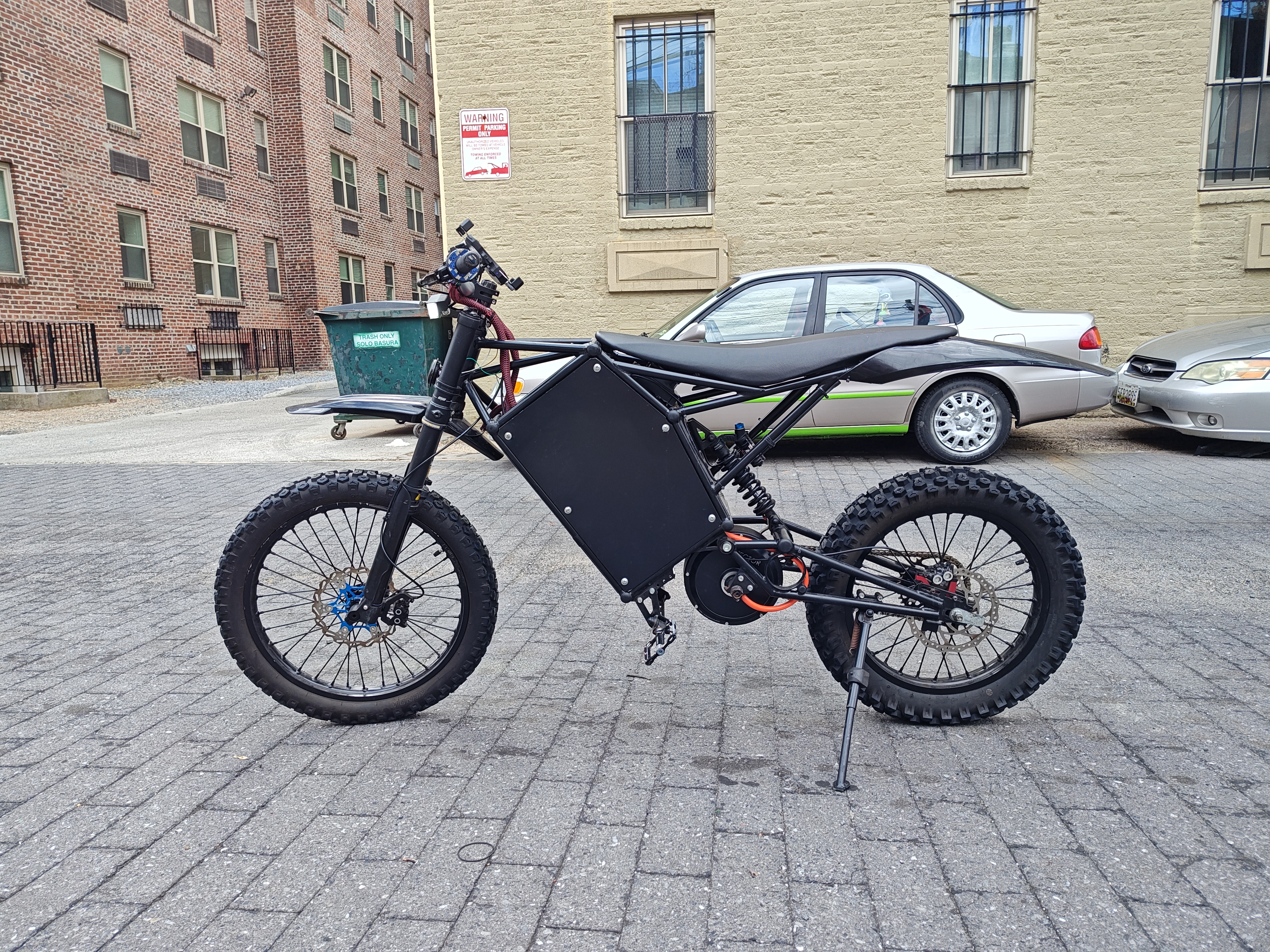
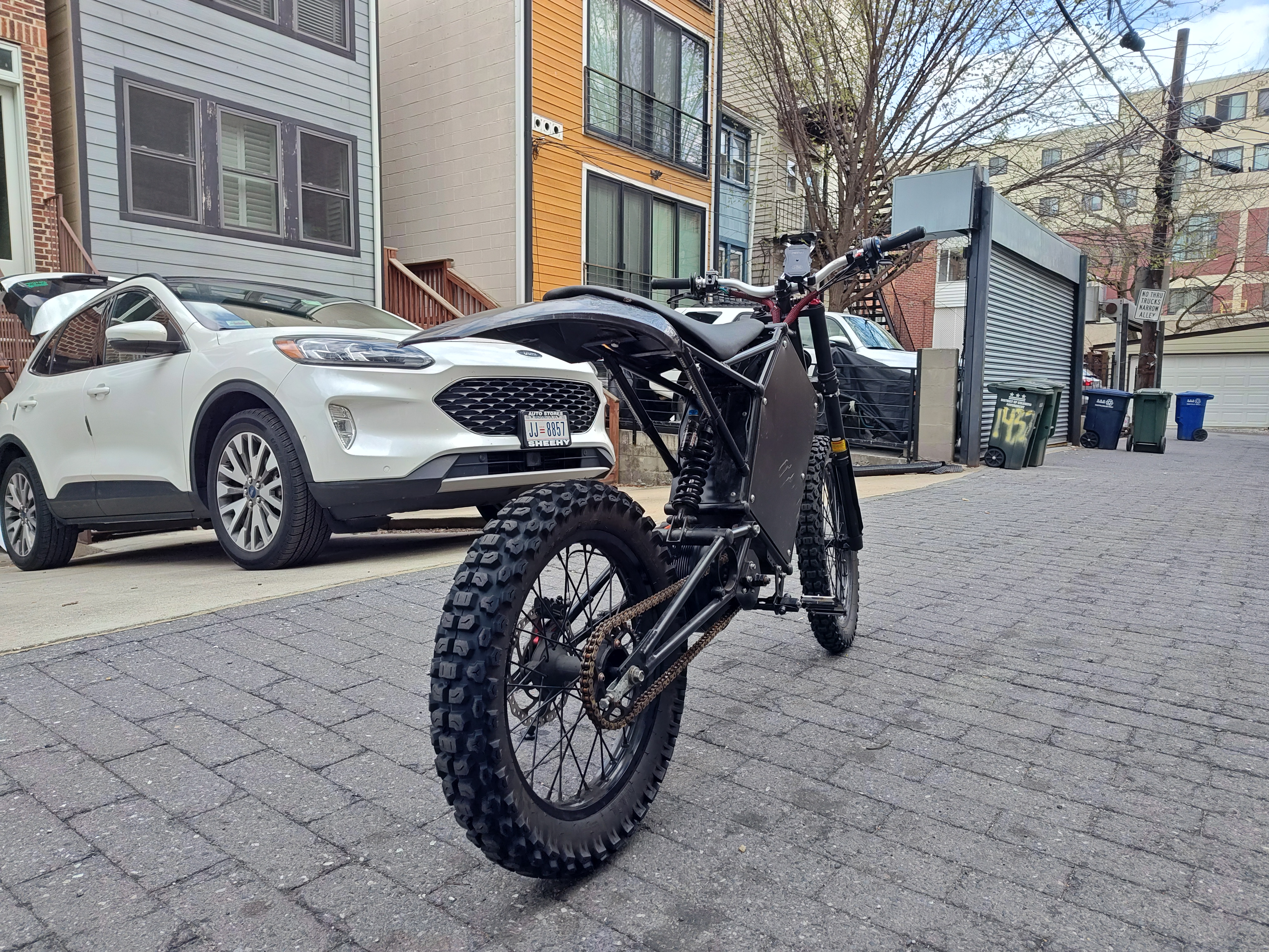
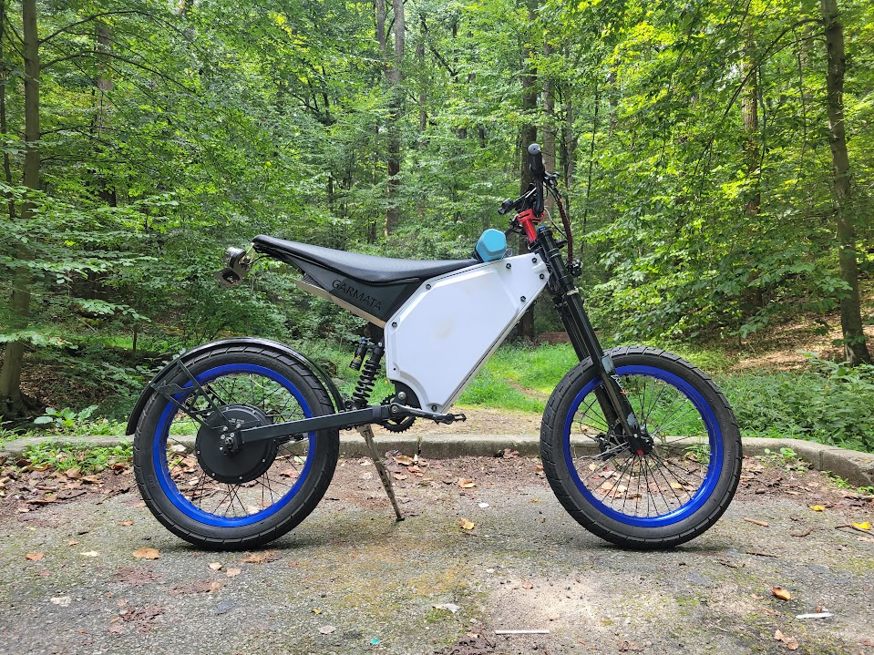
This off-road beast was designed to provide ultimate speed and performance. Everything from the knobby, dirt-ripping tires to the long wheelbase inspires confidence in the rider while maintaining supreme stability.
The active liquid cooling system for the controller allows the rider to push the bike hard all day without overheating. The quad-piston Magura brakes provide incredible stopping power with high fade resistance, aided by 2.3mm thick floating rotors.
With 32 kW of power on tap at all times, this monster can go from 0-60 mph in around 4 seconds. Overall, the high levels of stability, reliability, and performance make this bike an off-road conqueror.
This bike is built on an Eleek Positive frame, a model the Ukrainian military uses for their electric motorcycles. I chose this frame for its large battery compartment and center-mount motor options (my past bikes were all hub drives). Since the frame was built in and shipped from Ukraine, it took three months to arrive. In that time, I was able to design and build the battery.
Battery Build
I decided early on that I wanted a 96V architecture for the battery pack to increase efficiency under high load compared to my old 72V designs. The issue I found with 72V was that anything over 20 kW would drastically heat up motors and controllers due to the required current. To get more power, I needed to upgrade to 96V, a standard for off-the-shelf Battery Management Systems (BMS).
Another decision I made was that I wanted this battery to be incredibly efficient and overbuilt so it could be pushed all day. The first way I implemented this was with custom battery bus bars.
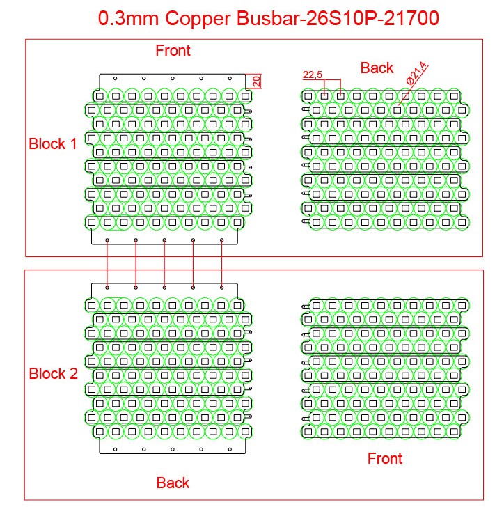
A 2D representation of the bus bars for manufacturing.
These bus bars were made of 0.3mm copper, which resulted in a total voltage drop of only 0.2 volts across all 27 bus bars in series. They were also great for manufacturing, as they have ultrasonically welded nickel tabs. This allows for spot-welding the nickel while still benefiting from copper’s low resistance (copper is notoriously hard to spot-weld).
I also decided to go with incredibly powerful but affordable cells, choosing the Samsung 40T for its $3/cell price tag (in 2023) and 35A power rating. All told, this pack could output 350 amps at 96V (33,600 watts).
The final piece of the puzzle was the BMS. I opted for an ANT 630A peak BMS since it was incredibly overbuilt and had integrated Bluetooth capabilities, all for a $100 price tag.
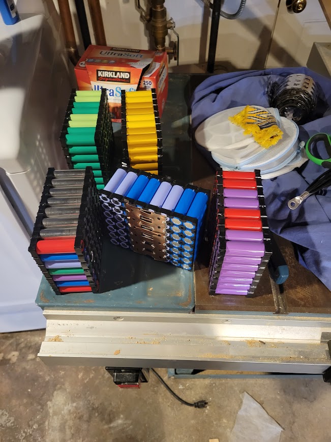
The cells in holders (left) and with the bus bars spot-welded on (right).
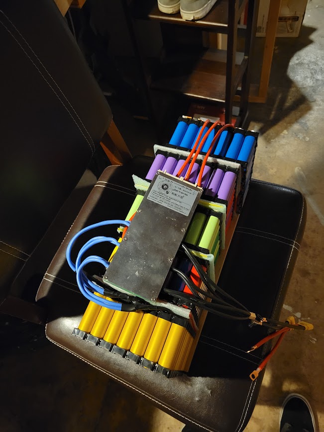
The battery with high-current wires installed, waiting for balance leads.
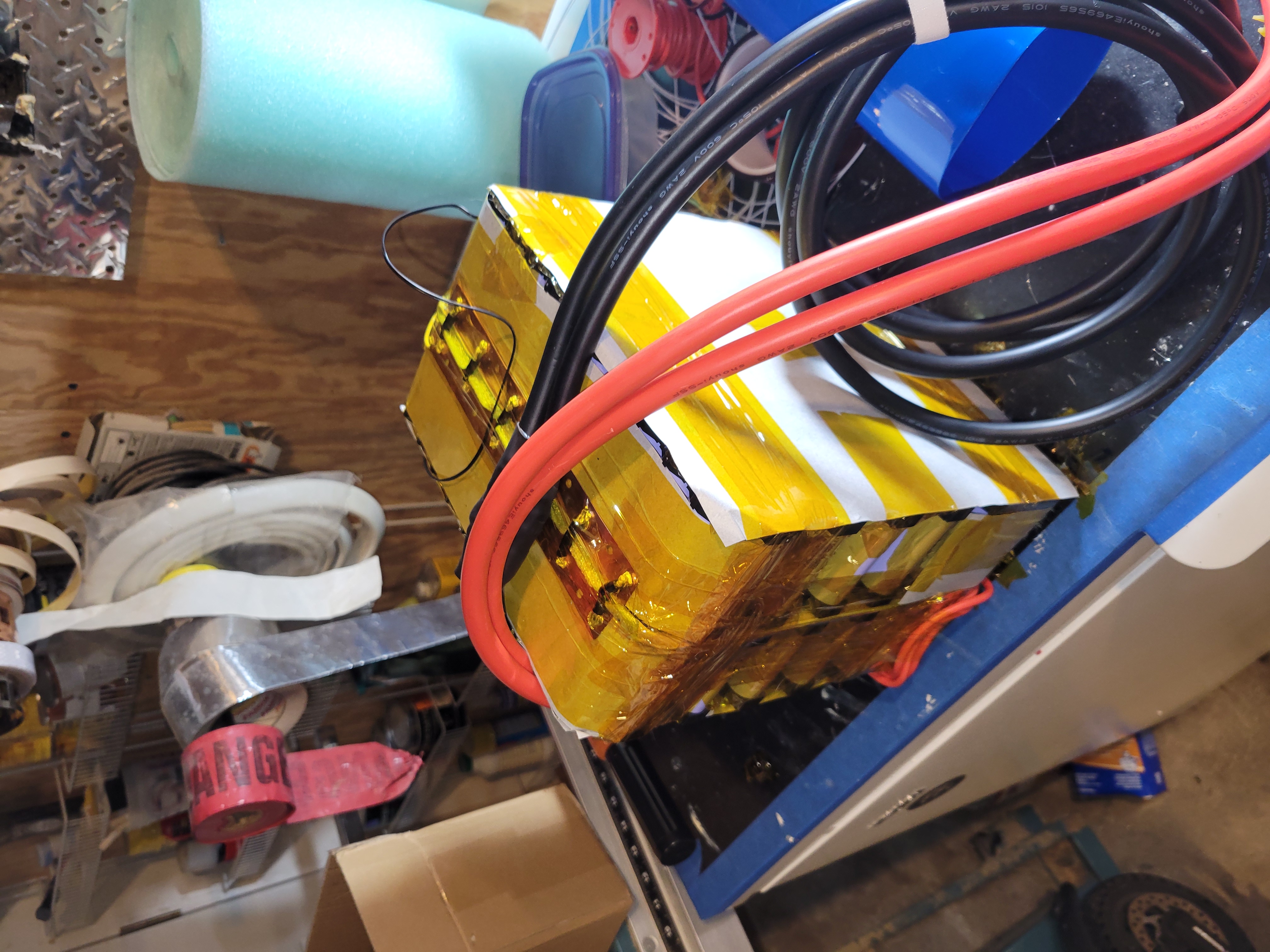
The battery almost finished (left) and fully wrapped (right).
Frame Assembly
After the frame arrived, I got straight to work. The battery was the most complex component, so assembly became easier once it was finished. The first thing I had to do was assemble all the mechanical components: wheels, motor, suspension, seat, swingarm, handlebars, and brakes. After integrating these components, I installed the battery and began creating the wiring harness.
A photo with all components integrated, waiting for the wiring harness.
The wiring harness was incredibly tricky to connect. The high-current path consisted of two 4-gauge positive and negative wires, which were very difficult to bend and move out of the way. I also had a cooling system with six half-inch tubes running through the same space. It ended up being somewhat messy but functional in the end.
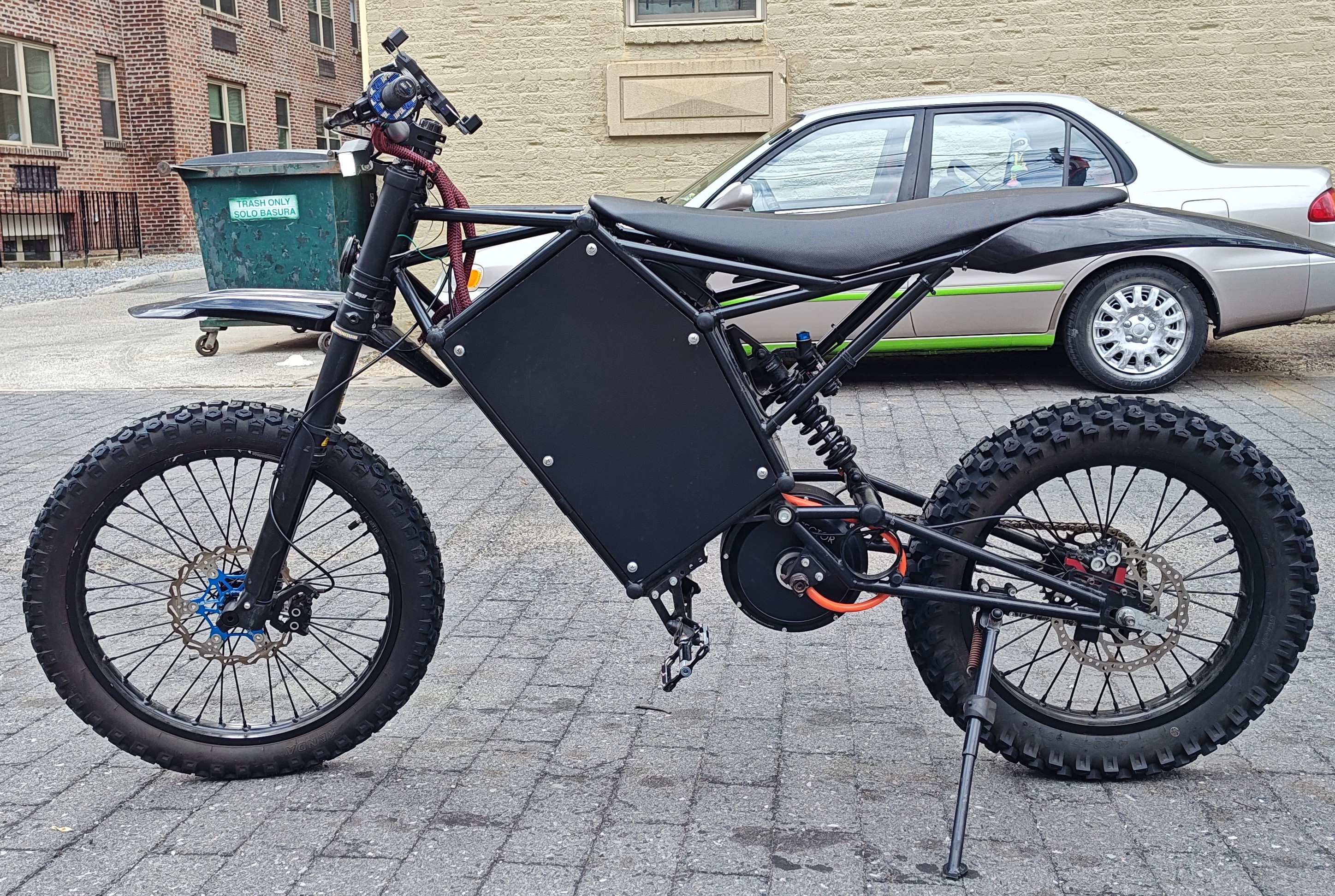
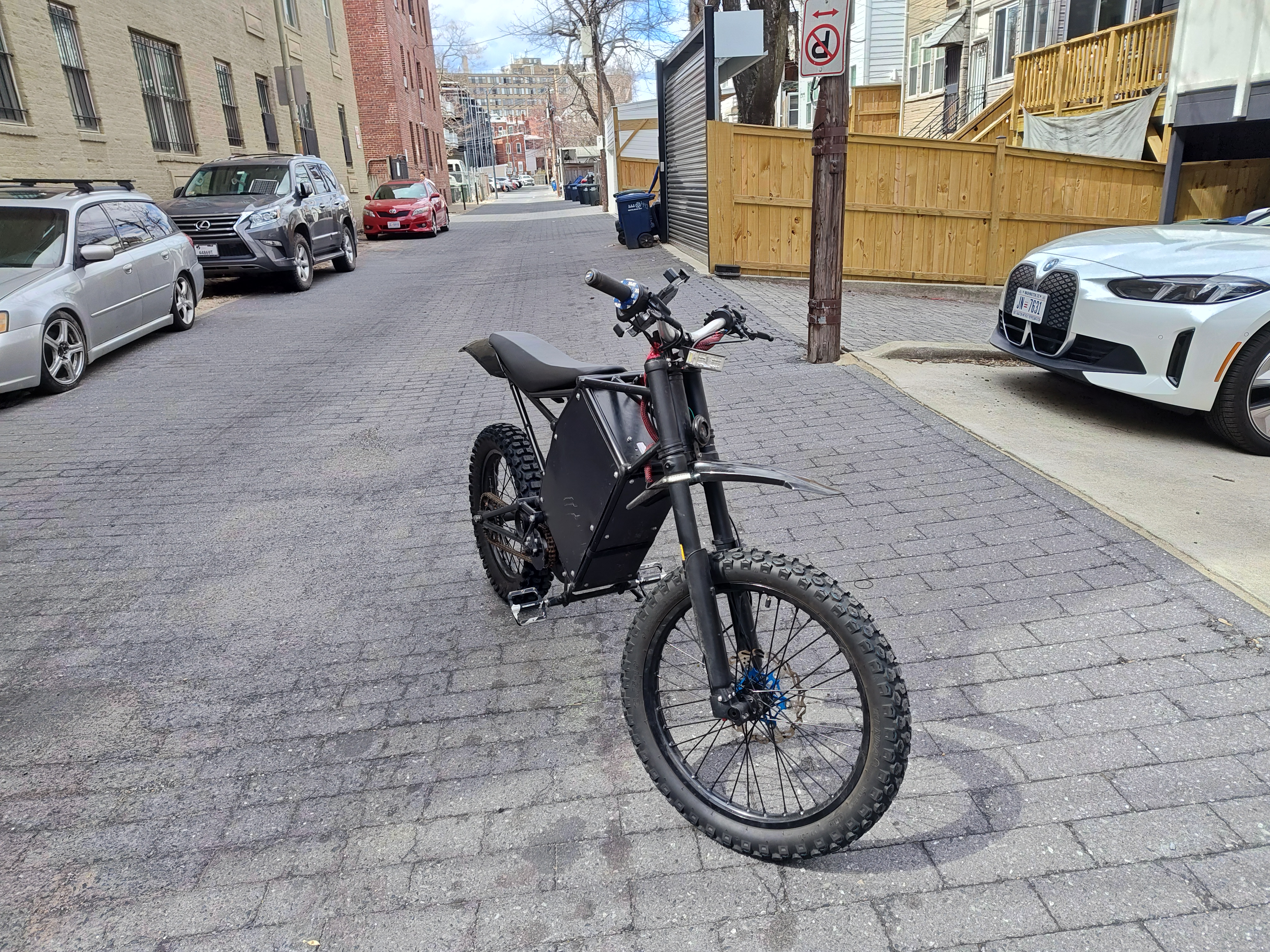
The bike fully assembled.
Reflection
This bike was the most intricate, powerful, and coolest motorcycle I have ever built. It taught me how to design efficient systems to prevent overheating, how to manage wiring with both large and small gauges, and, as always, it taught me patience.
If I were to do this project again, I would air-cool the controller and mount it externally to preserve room in the battery compartment for cleaner wiring. I would also make it less powerful and lighter. While this bike is incredibly fun to ride, you never use all 32 kW of power, and when you do, it’s terrifying. And while the bike weighed only 160 lbs, it would have been more nimble if it were lighter. Finally, I would have chosen a different motor, as the one I chose did not have enough torque at low RPMs and was therefore not efficient for low-speed hill climbs and other routine off-road maneuvers.
I ended up selling this bike to my school’s janitor when I left for college, as I no longer had a use for it. This bike remains my pride and joy and still holds a special place in my heart.
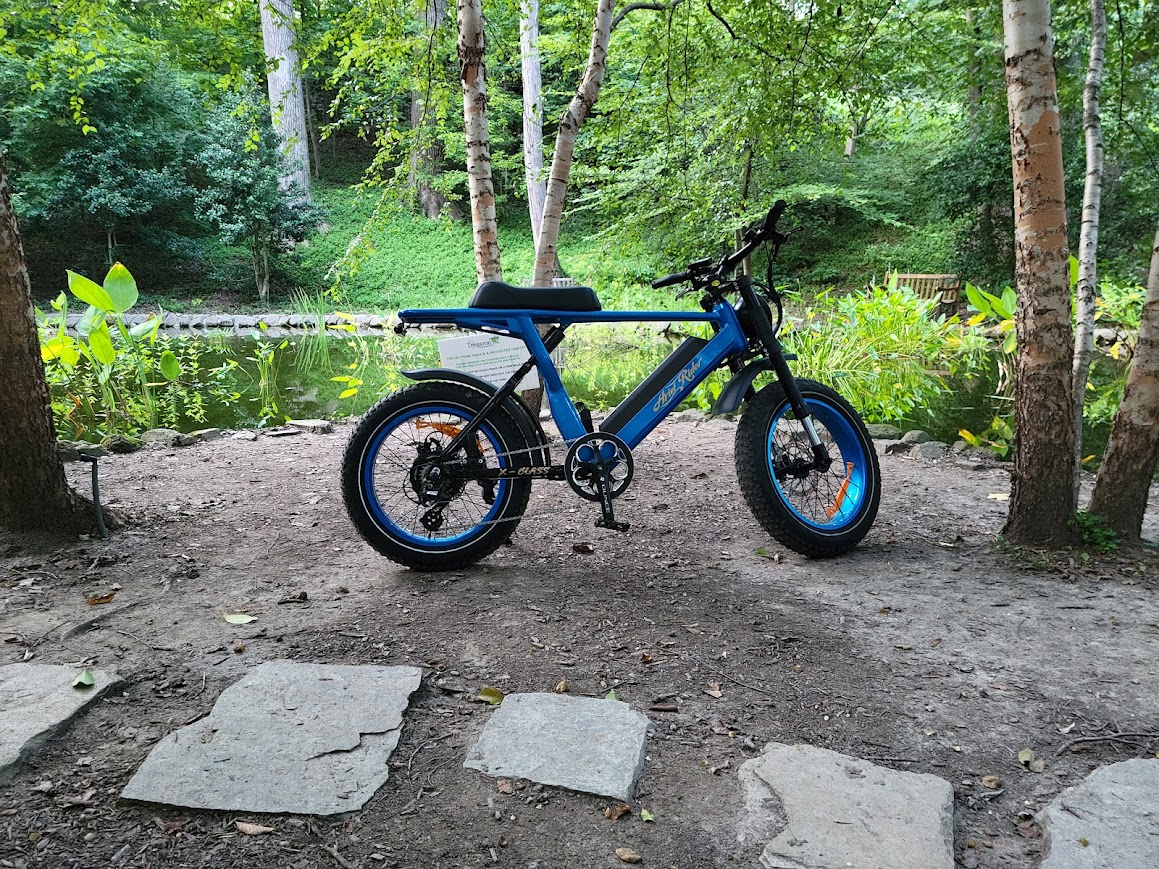
City Ripper
A lightweight electric commuter that puts gas bikes to shame.
Overview
The City Ripper was designed to provide the most fun experience possible in a small, lightweight platform that is perfect for all city conditions. This bike integrates long-travel suspension with sticky street tires that allow the rider to hop curbs, cut across grass, and hit potholes without a care in the world.
It has enough power to keep up with highway traffic for short sprints and enough torque to beat any sports car at a stoplight, all while weighing only 130 lbs. This bike is incredibly nimble and intuitive, whether you’re pulling a wheelie on a long straight or winding through stopped city traffic.
The bones of this bike come from a company called EEB, a Chinese factory that sells frames and components directly to the consumer. This is their “Enduro” frame, which is designed for long-travel suspension, a large battery, and a hub motor. I selected this frame because it was lightweight at only 22 lbs (8 lbs less than the motor alone). EEB is also known for high-quality welds on its frames, good customer support, and a wide range of accessories, along with standardized components for easy off-the-shelf assembly.
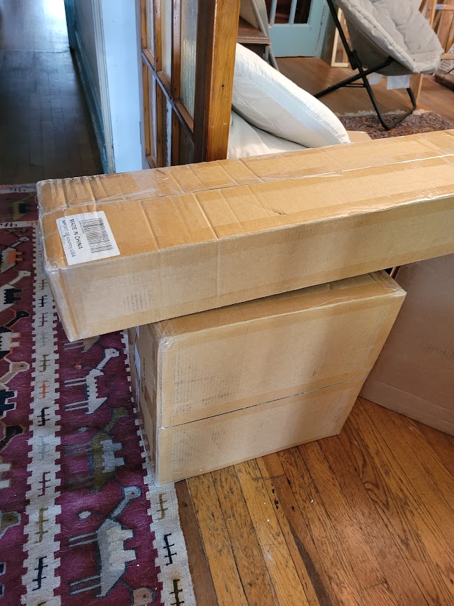
To start the build process, I purchased the frame, plastic panels, suspension, wheels, and motor from a variety of suppliers.
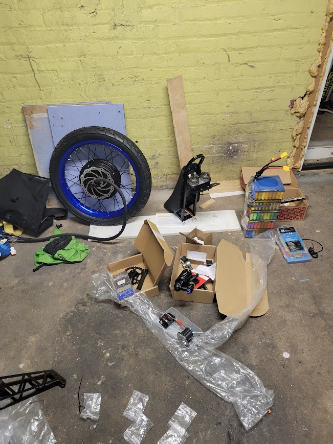
A selection of suspension parts, the battery, and the motor for the bike.
After about three months of waiting for all the parts to arrive, I started to assemble! This process proved tricky since I did not have professional bike shop tools and was forced to create some janky assembly setups.
The front suspension on a regular bike stand.
The suspension and frame assembly went relatively smoothly, as it was a process I had done a couple of times before when replacing the suspension on my Sur-Ron motorcycle.
The bike mostly assembled, without a wiring harness.
The two major assembly challenges I had with this bike were the battery and the controller.
Battery Build
I built the battery for the bike in a flat configuration with the idea of folding it to create my desired shape.
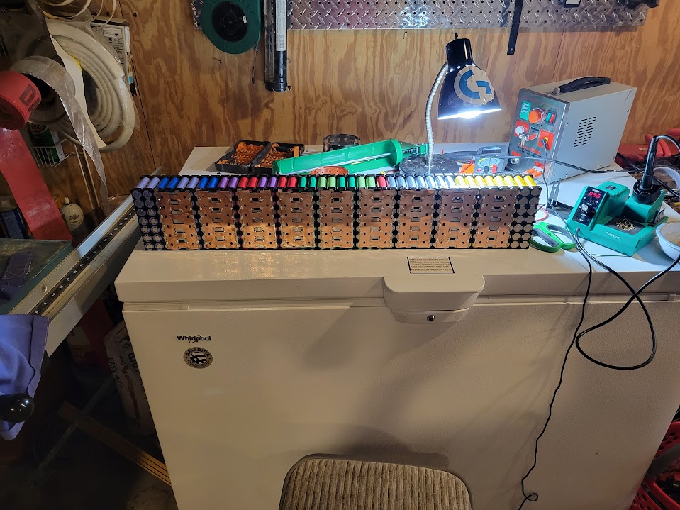
The battery in its flat configuration, pre-folding.
While my concept was solid, I ended up placing the folds in the wrong places, so the battery wanted to fold in on itself, not stack. This was incredibly disappointing, as I had to then cut the battery back into its individual segments and solder them together independently.
The segments of the battery separately (left) and then soldered together (right).
In the end, the battery turned out perfectly and met my design requirements for weight, voltage, and capacity.
Me standing with my finished battery.
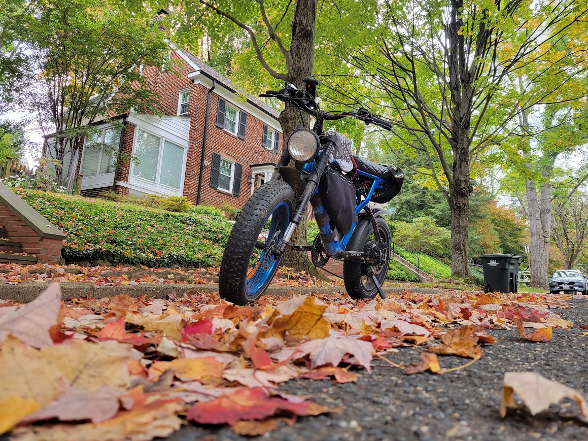
With the battery finished, I was then able to assemble the rest of the bike and get to riding!
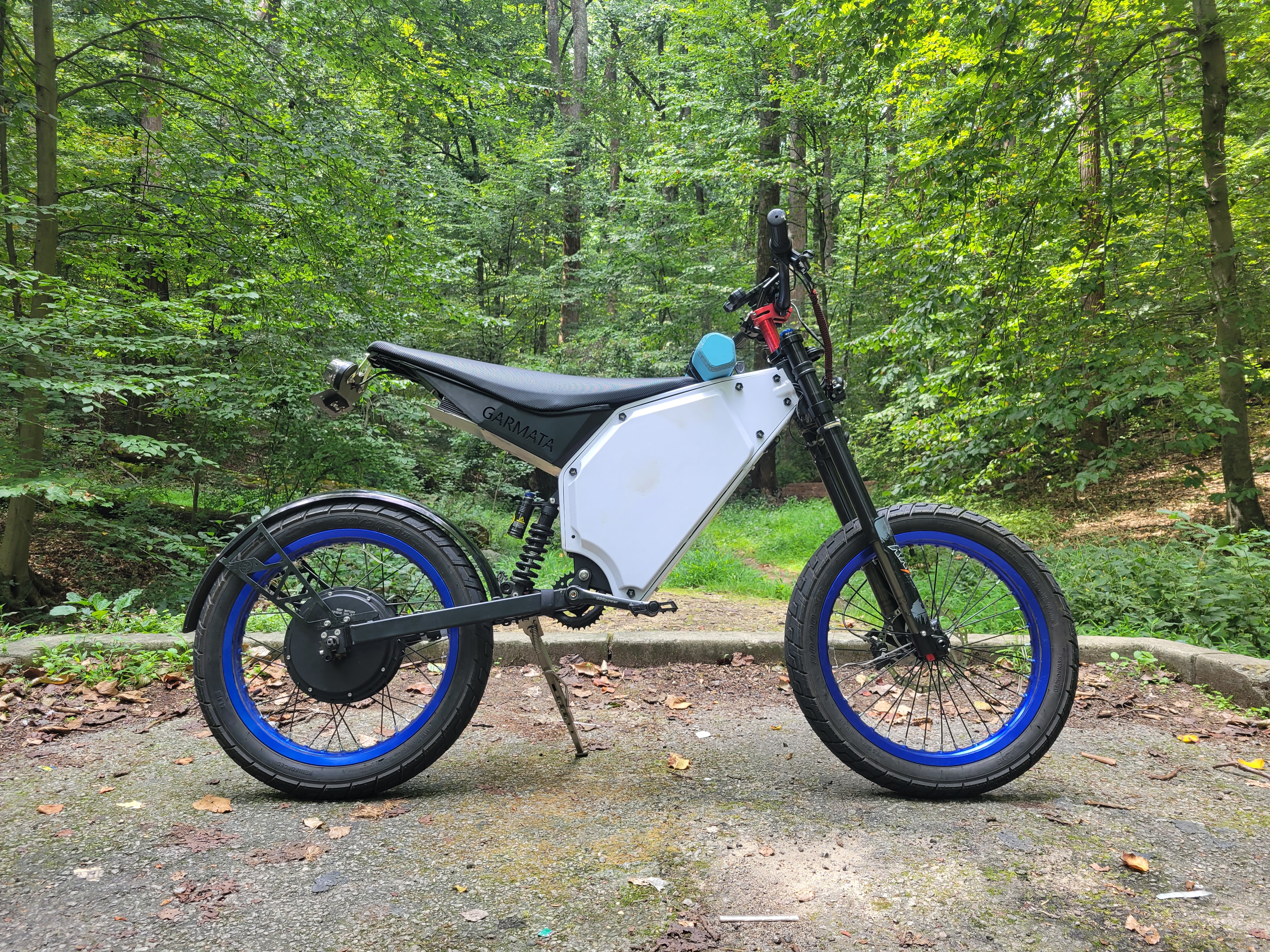
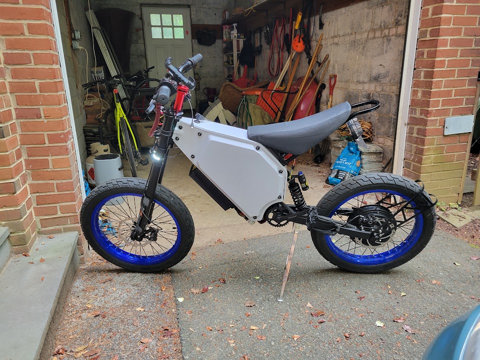
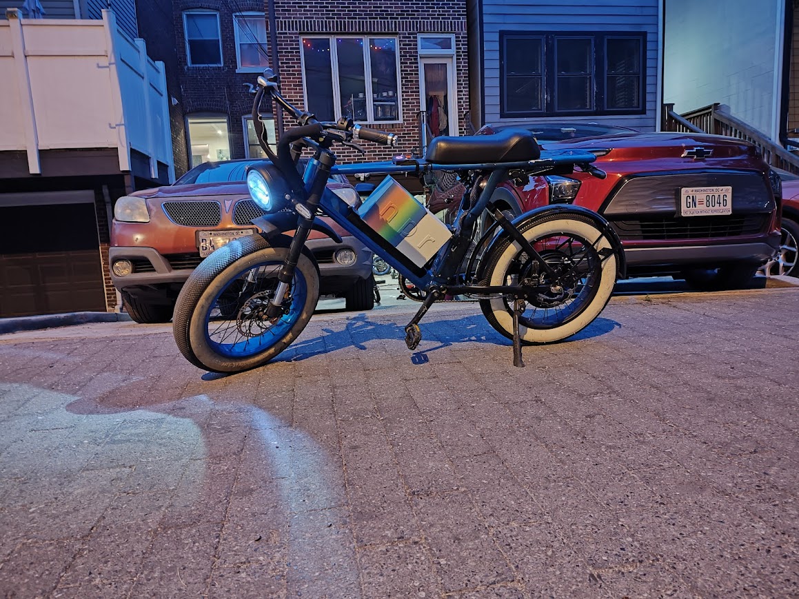
The finished bike in front of a friend’s garage.
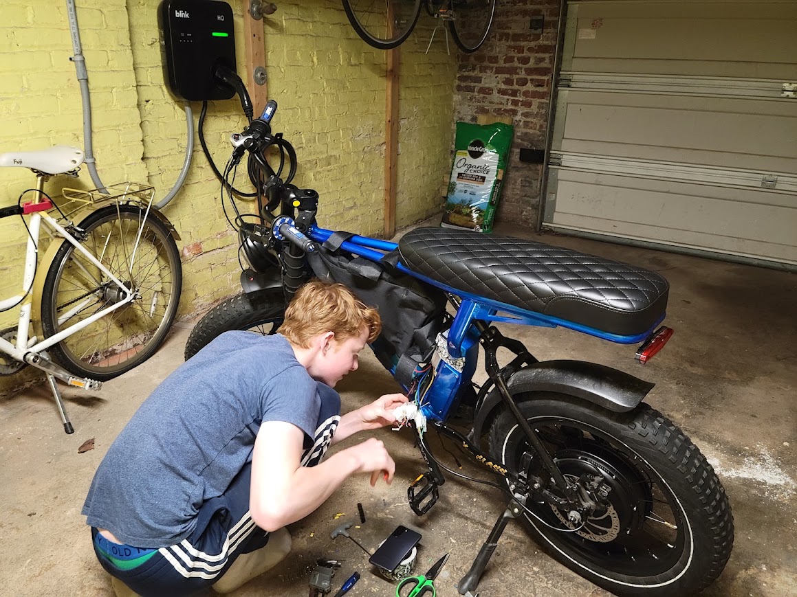
Controller Troubles
The other big issue I had besides the battery was the controller. The controller I initially used was a Sabvoton SVMC72200. While this controller used to be a go-to for high-powered bike builders, the company had recently come under new management, and quality had decreased. As of this writing, I have burned through three $450 Sabvoton controllers, which has been quite infuriating.
While riding to school one day, I was accelerating quickly from a stoplight when all of a sudden my rear wheel locked up and the entire bike shut down. There was also a good deal of magic smoke coming out of the controller (the gray box underneath the front part of the frame, seen in the last picture). From a post-mortem analysis, I concluded that one of the MOSFETs had welded itself to the cooling plate. This caused the motor to act like a completely shorted generator, thus locking up the rear wheel. The other two Sabvoton controllers failed in the same way about a year or two later.
After this failure, I switched to Fardriver controllers due to their low cost, high power, FOC technology, and Bluetooth capabilities. I was absolutely blown away by the build quality and features for the price, and they are now my go-to controller for any project.
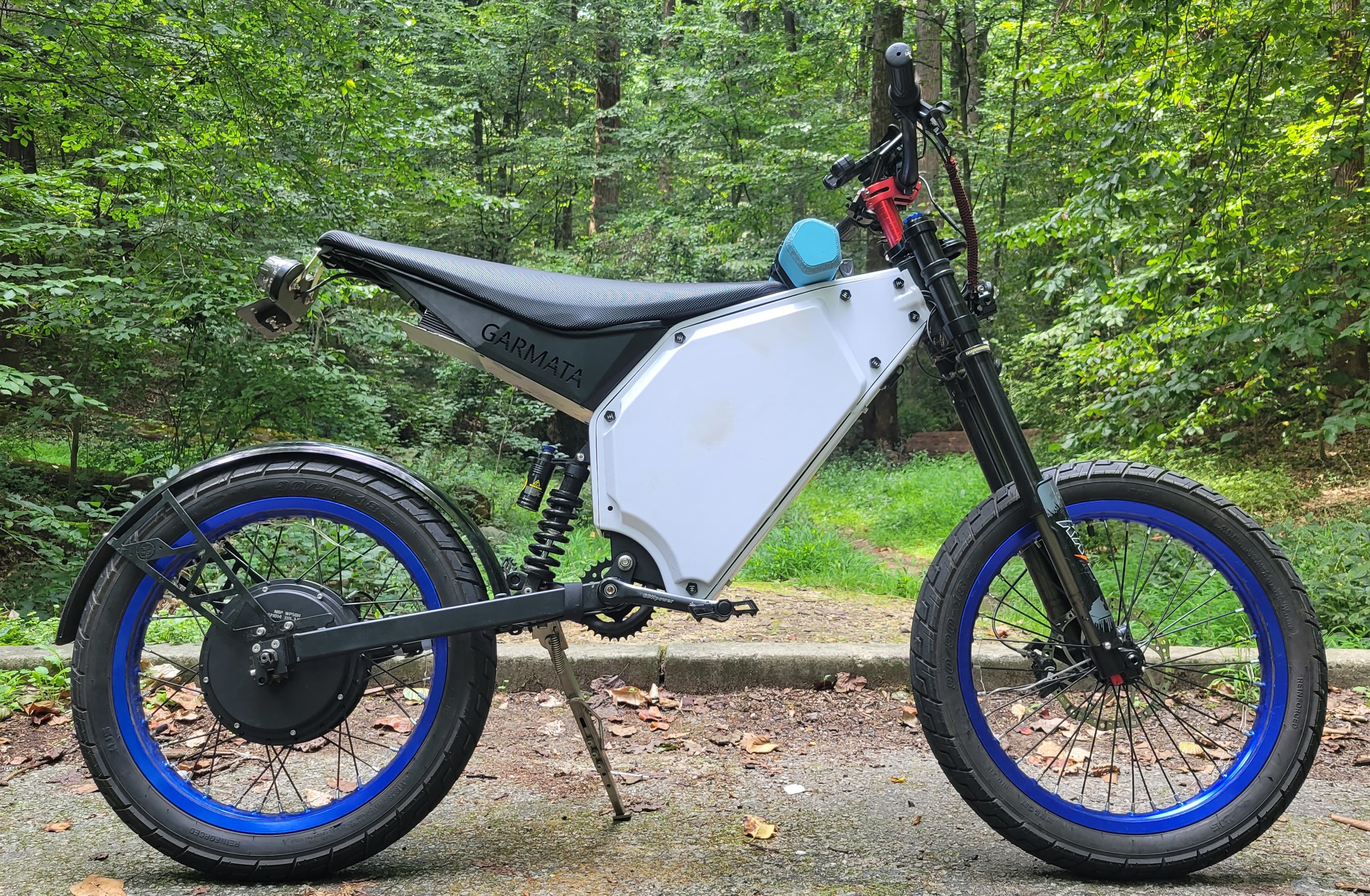
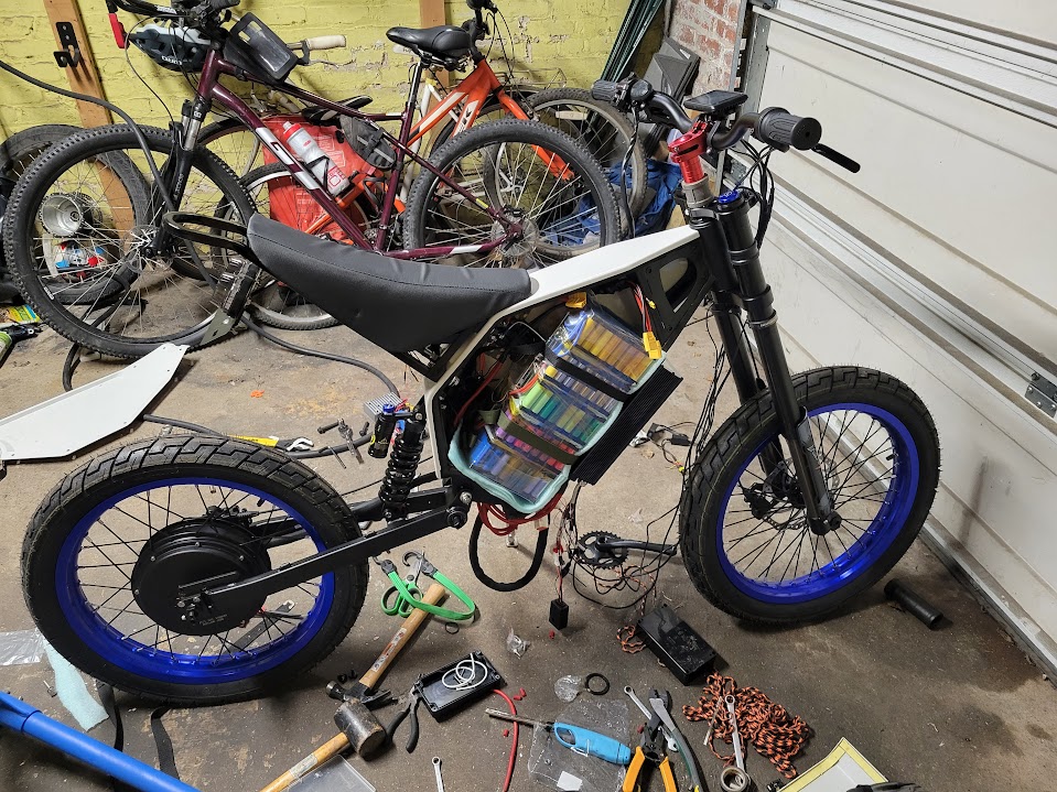
The bike with the new Fardriver controller and a new seat for housing it.
Mom-Mobile
An ATV for my mom, who gave me my love of speed.
Overview
An ATV is a fun, easy-to-ride farm vehicle that even the tamest of riders can feel comfortable on. But what if you want more?
My mother was not satisfied with a pokey gas ATV and wanted an upgrade for touring her property. She challenged me to build a dead-quiet, long-range, and fast ATV that could tackle any terrain, and so I built one!
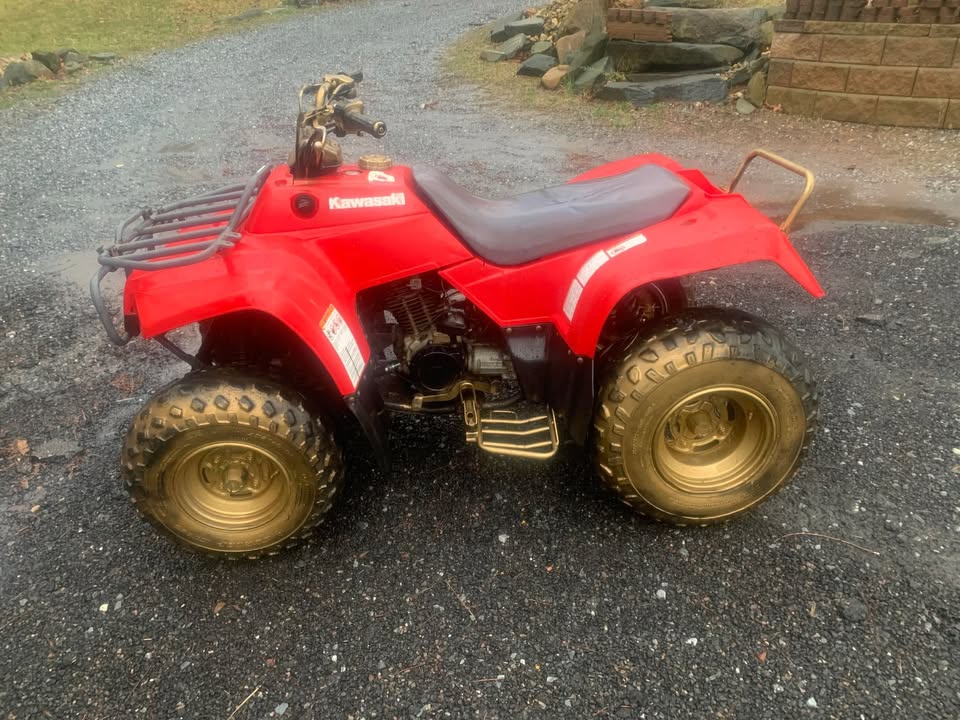
The ATV had humble beginnings as a 1997 Kawasaki Bayou 220 that had seen many better days.
The Facebook Marketplace listing photo for the ATV.
I purchased the ATV, in non-running condition, from Facebook Marketplace for $500. It was rusty, spray-painted an atrocious gold, and was overall a bit sad. Before I could do anything else, I needed to clean it up.
Cleaning and Painting
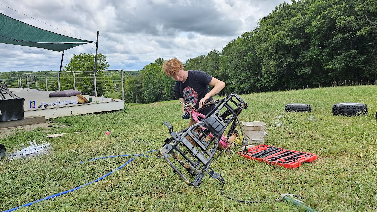
I ripped absolutely everything off the ATV. The only thing left at the end was the bare frame. I took a wire brush, detergent, and a garden hose and spent a whole day cleaning all the parts I wanted to re-use.
Me working on taking off the final suspension members during cleaning.
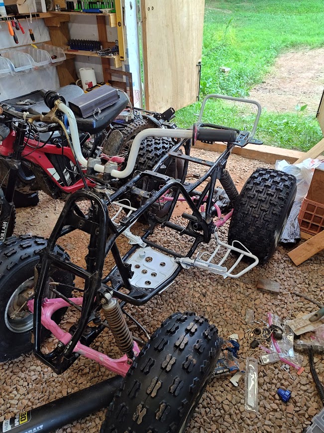
I really wanted to re-paint the entire frame, but I did not have the resources to strip all the paint off, wire-brush everything, and then repaint it cleanly. The frame was also in fine condition, so I left it. Seeing as my mother’s favorite color is pink, I had to repaint some parts to fit her aesthetic.
The frame and suspension of the ATV after painting.
I also planned to paint all the body panels in camo-pink but decided I needed to learn more about painting before diving into that project.
Battery and Electronics
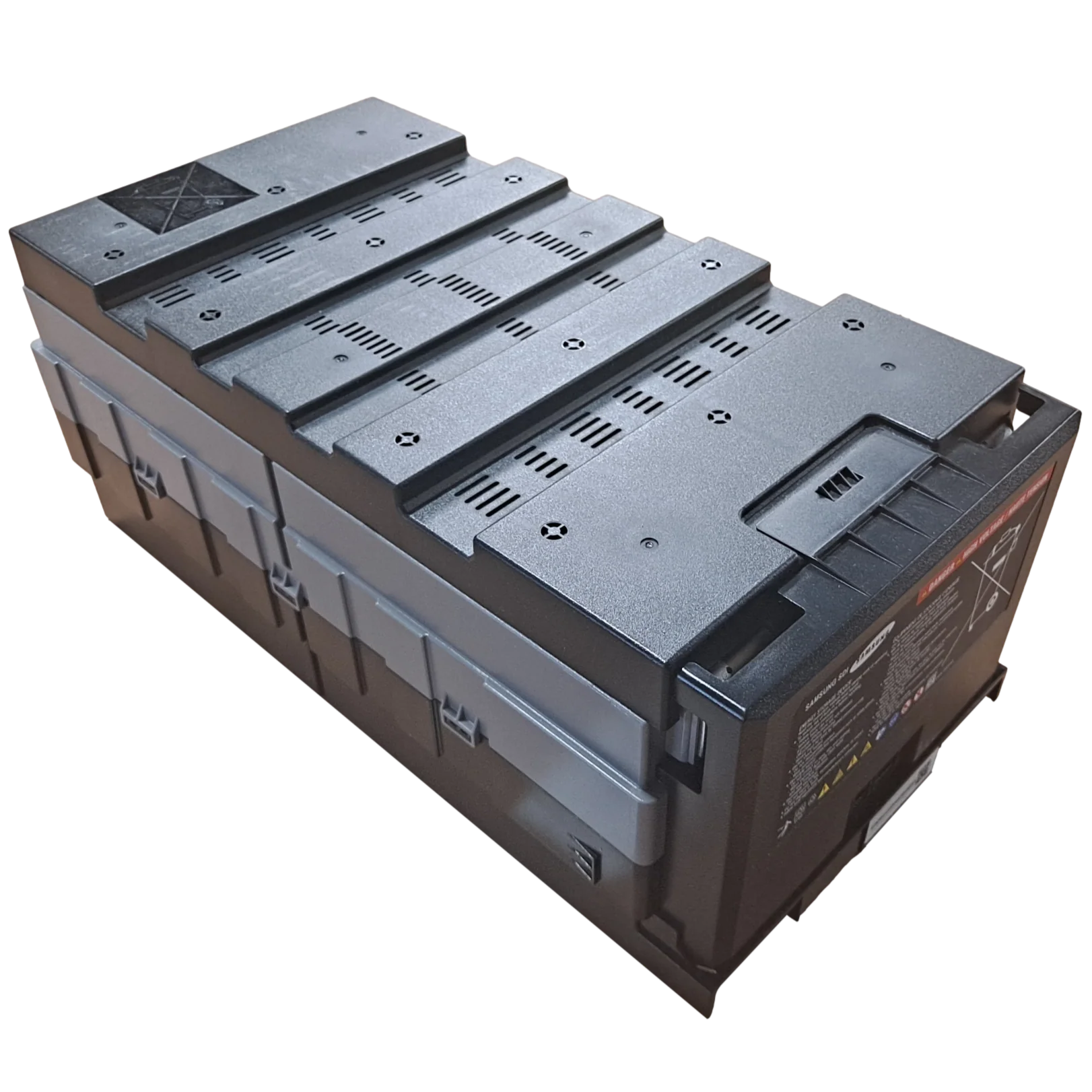
Range anxiety really takes the fun out of riding, so I wanted this ATV to have way more range than necessary. To accomplish this, I purchased two Samsung 8s 67Ah prismatic cell modules and wired them in series. This provided a total energy capacity of 3,966 Wh.
The battery listing photo at Batteryhookup.com.
To manage this battery, I used a JK 200A continuous BMS since it perfectly aligned with the 200A controller, and JK is well-regarded in the battery-building world. While I prefer ANT BMSs, I opted for the JK since it had 1A balancing instead of the 180 mA found on the ANT. The larger cell capacity needed the higher balancing current.
Originally, for the controller, I went with a Sabvoton SVMC 72200, like on the City Ripper. But, as with that controller, I had a MOSFET short to the cooling plate underneath, and the controller went up in flames. So, I purchased a newer Fardriver 72450 that had the same power specs, a better interface and features, and was less than half the price.
A basic wiring harness with the new Fardriver controller (blue box).
Motor Integration
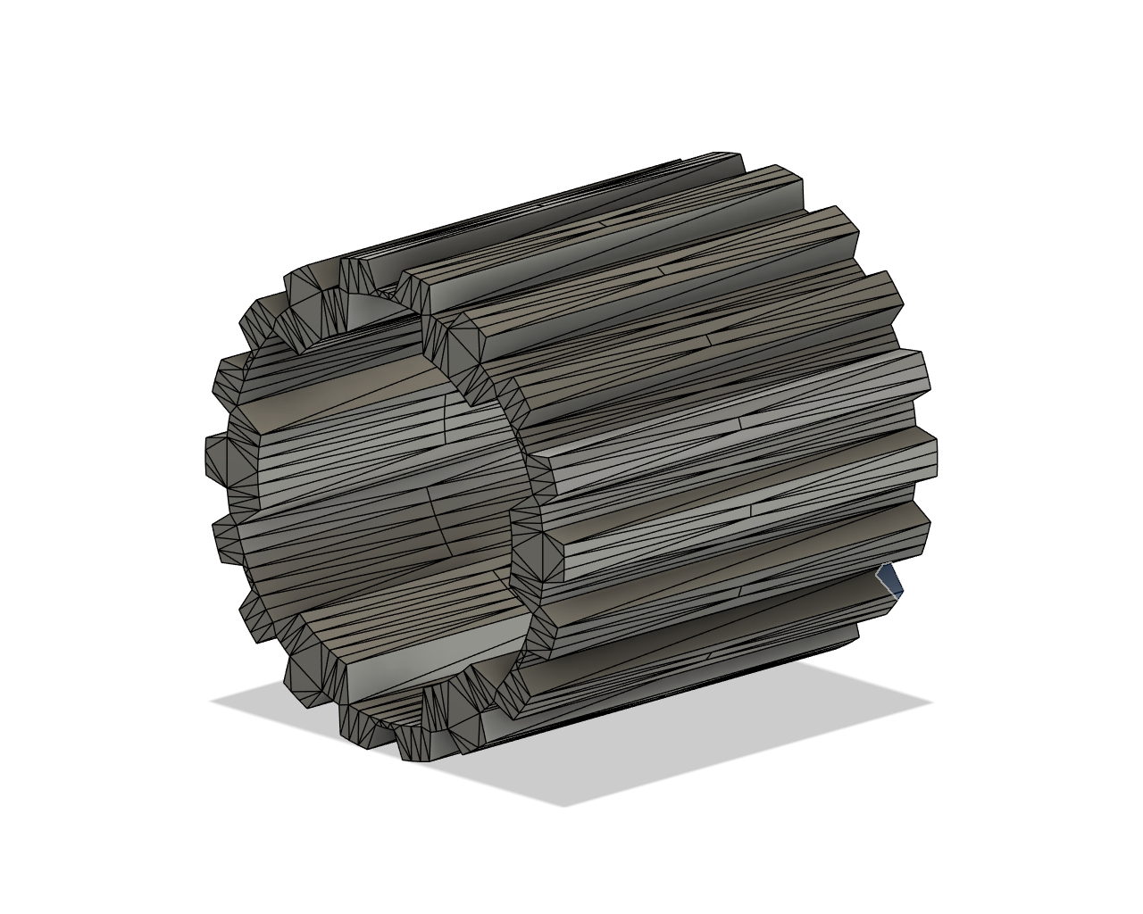
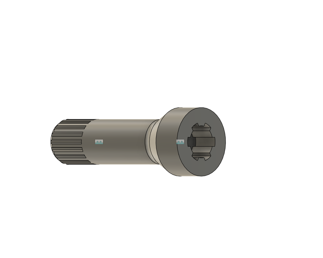
Integrating an aftermarket motor made with Chinese manufacturing standards into a 28-year-old Japanese ATV was really hard. The biggest challenge I faced was making a spline adapter that went between the motor’s output shaft and the rear differential’s input shaft.
I created four different adapter designs before I found the perfect fit for the splines. I made the first three adapters to try and fit the motor to a 90-degree gearbox and have the motor transversely mounted, but I could never get the gears to mesh correctly. I then switched to having the motor mounted inline with the driveshaft, which worked much better.
Spline adapter v1 (left) and spline adapter v4 (right).
The motor mounted with adapter v4 and final mounts.
As a small side note, I ordered the final adapter just as tariffs on Chinese goods hit, which forced me to change manufacturers. The quality of the final product was not as good as I hoped. The tolerances on the motor spline were slightly off, which led to 1.5 hours of hand-filing to get the right fit.
Final Assembly
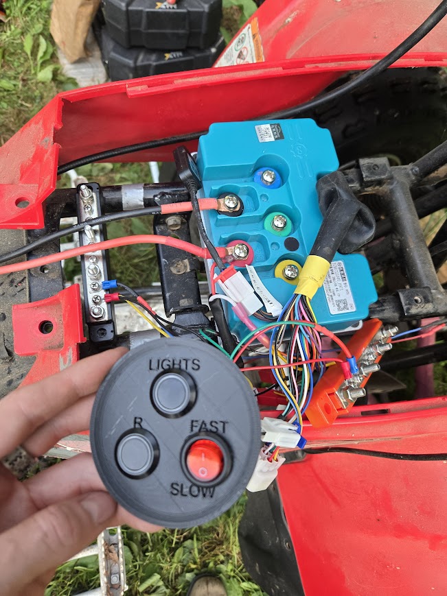
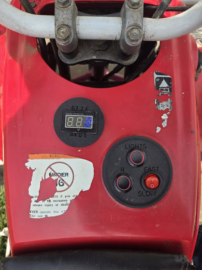
After mounting the motor and final spline adapter, I was able to finish up all the wiring and put the plastic panels back on. During my final wiring, I realized my 12V converter was too small. The headlights alone drew 12 amps, and the converter could only supply 10 amps, so I had to do some rewiring, but nothing major.
Control panel and voltage display with a light switch, reverse, and 2-speed modes.
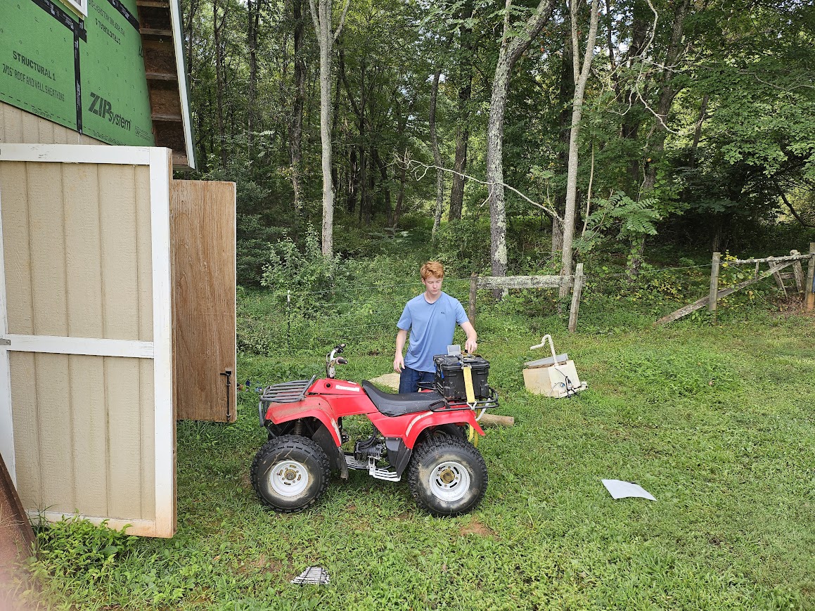
Me tweaking the battery mounting on the almost-finished ATV.
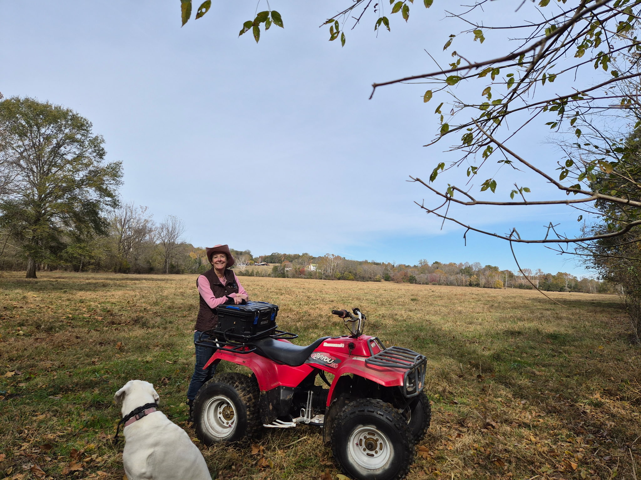
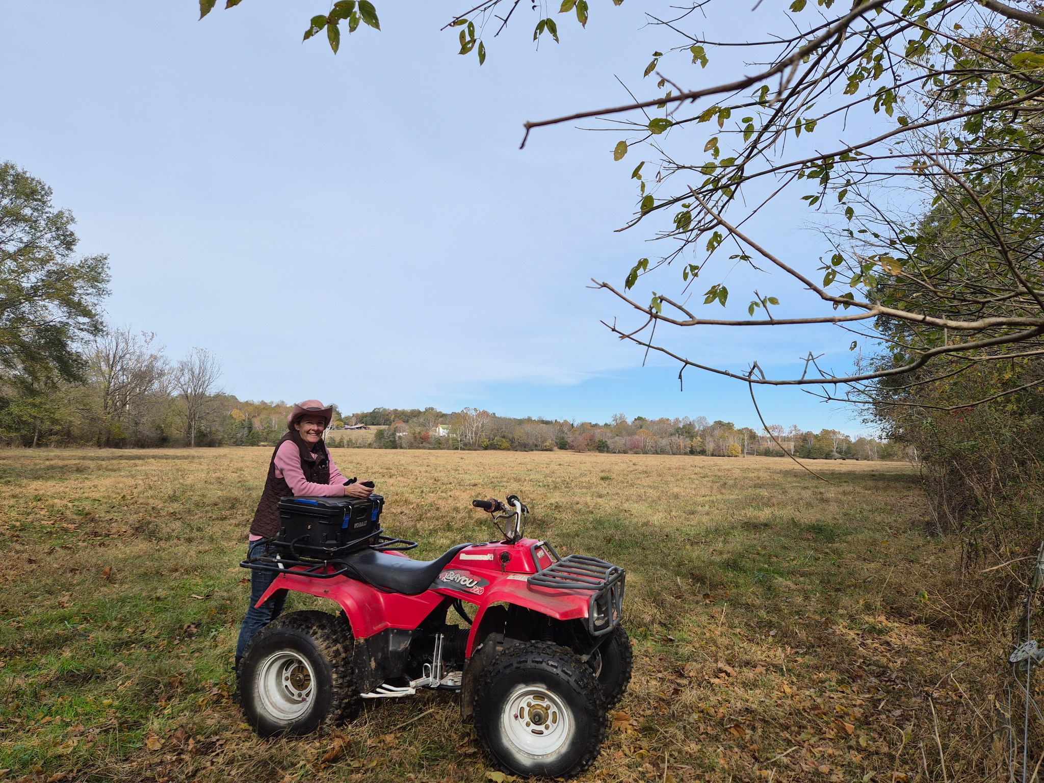
My mom out for a ride on our farm.
I have yet to do the final painting or battery mounting, but the ATV is now rideable, and my mom absolutely loves it.
Reflection
This project came with some of my biggest setbacks, except for the bike that caught fire. It took almost a year and a half from start to finish due to everything from laziness to tariffs. It really pushed my limits of designing for manufacturing and my engineering knowledge in general. I failed many times with the gearbox and my spline adapters, but I always made another version.
Seeing how happy my mom was with the final product made it worth all the trouble. The final ATV was quiet enough to have a normal conversation while riding and fast enough to pull a wheelie when necessary. It could go through foot-deep mud and up rutted hills without complaint. While this project did have many of my biggest failures, it was nevertheless an incredible success.
Blueberry
The bike that started it all.
(This is the essay that got my into Olin with pictures added.)
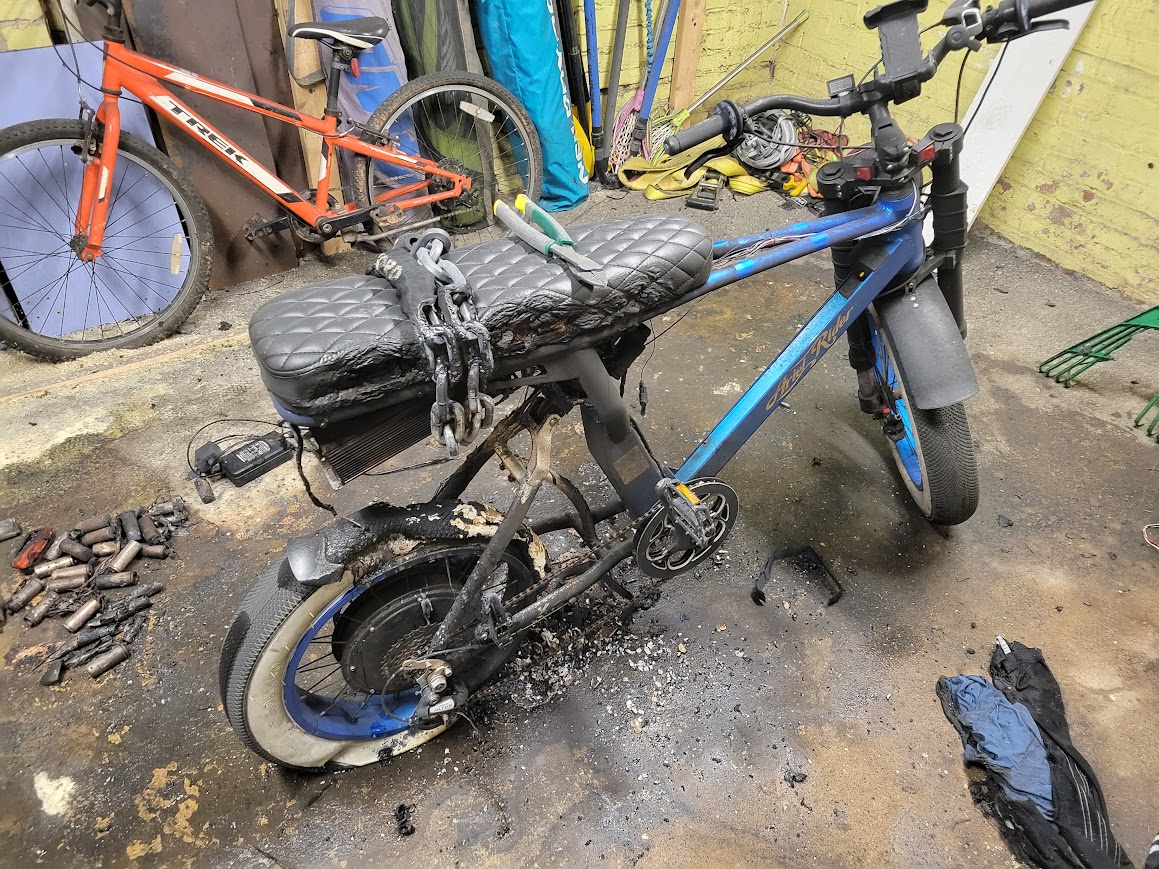
Instead of coffee to start that February day, I had fire to wake me up. It started at 4am with my mom banging on my basement bedroom door yelling that the garage was on fire. I ran out of bed, up the stairs, and out to the driveway where black smoke was billowing out of the garage. For a minute I did not process what was happening, but then, through the clouds, I saw orange flames in the shape of a bike. This e-bike was mine and its name was Blueberry. For more than two years, I’d been saving, building, and re-building my precious e-bike, which in the matter of an hour was gone. (The fire was in the concrete garage, the rest of the house was undamaged.)
Blueberry started life as a normal e-bike doing normal e-bike things. During the pandemic, we relocated to rural Virginia and I worked around our family’s farm and saved money to buy this bike– the shimmering blue paint and motorcycle styling had me hooked.
Blueberry and I had a good six months together. Blueberry happily chugged along as my daily commuter bike. I went to school, took every opportunity to explore DC alone, and went on long rides around DC, Maryland and Virginia with the e-bike community I found.
Then I got the upgrade bug. It started when a key component in the battery failed and I had to fully tear down the bike to fix it. Looking at all the parts made me realize I could make this one bigger, make that just a bit better. And so, I did.
I went into the land of high voltage batteries and powerful motors supremely excited but with a lack of caution. This manifested in that I blew up my first motor controller (the brain that tells the motor how fast to go), and the next, and then the next ones were poor quality since I did not know what to look for, and lo and behold they sparked and died too. Finally, on try number five, I was successful. I had re-wired the bike two if not three times, and had upgraded a plethora of other components, so Frankenblueberry was doing quite well–except for not having a brain. But controller/brain number five got me up and running and I was overjoyed. My ideal vision for Blueberry was getting closer and for another 9 months, I rode and modified. I also started a business repairing e-bikes with Blueberry as my company logo. Jake’s E-Bike Repair and my love for fixing bikes and building them stemmed from my failures and successes with Blueberry. I’d learned how to build batteries, wire controllers, and program an e-bike, as well as work on tires, brakes and derailleurs and I continued to tweak Blueberry to be closer and closer to my vision until I was mostly satisfied.
Then came that fateful morning where I watched as my pride and joy burned to the ground. I’d upgraded the battery with poorly-made cells and they gave out while charging that early morning.
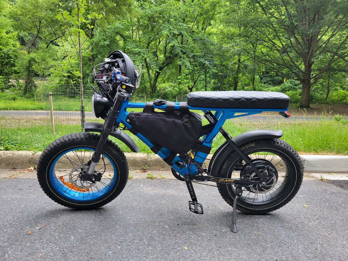
The charred frame of Blueberry still sits in the corner of the garage. I’ve built myself a new bike from scratch, and it’s the perfection I had envisioned (with high quality battery cells!). I paid for it all with my repair business earnings, and I built it with my knowledge, both of which started with Blueberry. This is not the end of the road, however. Blueberry was severely damaged, but not completely broken. I am rebuilding it for my dad. The only parts of old Blueberry that will physically remain are the frame and the front wheel. But the bike will still be Blueberry. It is still built on the spirit of perseverance, it is still teaching me new things, and it is still that little bike that got me started two years ago and changed my life.
FSAE Projects
Projects for Olin Electric Motorsports.
Power and Thermistor Board
A custom PCB for measuring cell voltage and temperature.
Project Management (ongoing)
The trials and tribulations of running an FSAE team.
Throttle Firmware
Writing throttle logic and fault handling.
Power and Thermistor Board
A custom PCB for measuring cell voltage and temperature.
Overview
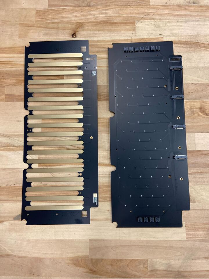
Our FSAE team uses a 102s4p battery broken up into six segments of 17s4p. Each segment has its own balancing/monitoring board, data acquisition board, and a power and thermistor board. On our previous car, Mk6, the power board and the thermistor board were separate. The power board connected all the cell groups in series and carried the pack current to a REDCUBE connector on each end, while the thermistor board measured each cell’s temperature. My challenge was to combine them while maintaining rules compliance and functionality.
Mk6 power board (left) and thermistor board (right).
Project Requirements:
Follow all FSAE rules and best practices.
Combine the power and thermistor boards into a single PCB.
Fit the existing accumulator segment’s mechanical constraints.
Maintain connector placement compatibility with the BMS motherboard.
Project Deliverables:
A complete PCB schematic and layout with the following components:
Thermistors for temperature sensing.
Copper strips and traces for voltage monitoring.
Three 20-pin connectors to send signals to the BMS motherboard.
Fuses located within 20-25mm of the copper pads.
Normally open solder points.
Design Process
Before this project, I had never designed a PCB. I had experience with circuits and wiring, but never a full PCB from scratch. I broke down this problem into three sections: Mechanical Fit, Electrical Functionality, and Design Quality.
Above all, my design needed to fit the accumulator segments; without this fit, the board was obsolete. To ensure this, I got a DXF board outline file from the Accumulator team and we discussed which parts of the outline could be changed and which could not.
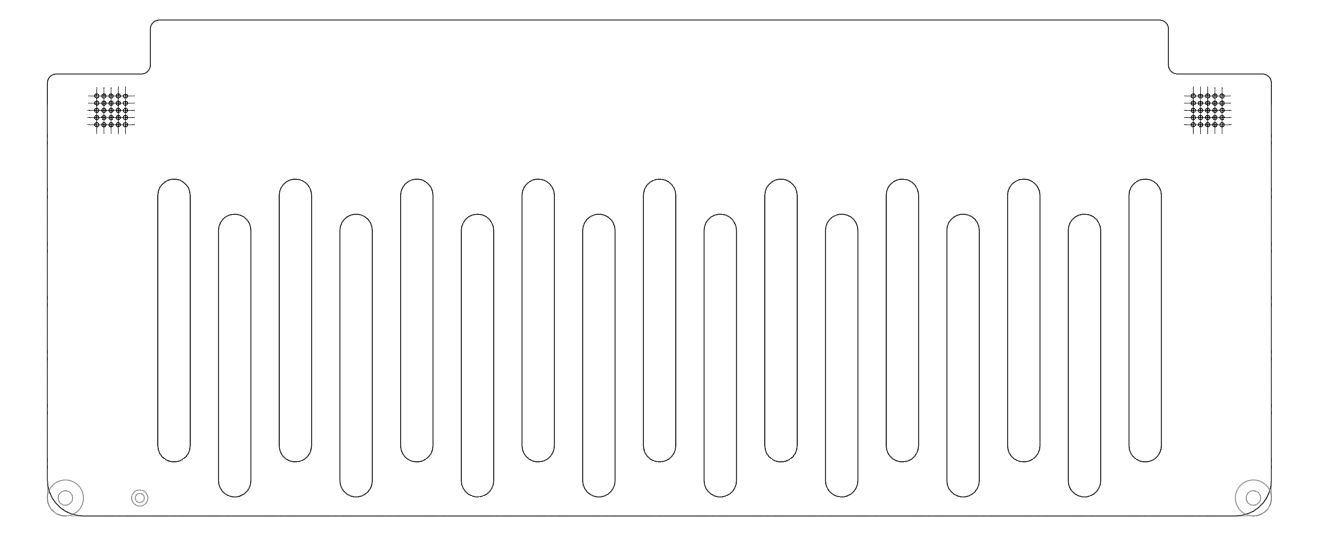
The original board outline at the start of the project.
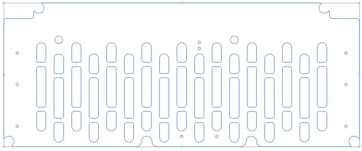
After about an hour of looking at this design, I was convinced it would not work well. I would have had to place the thermistors offset from the negative terminal, which would have required extensive use of thermal compound to connect them thermally to the cells. I went back to the Accumulator team and suggested adding small bridges in the middle of the gaps to place the thermistors on. After a quick meeting with our electrical and mechanical leads, we decided it was feasible and came up with a v2 design.
Board outline v2.
After finalizing the outline, I was able to finish my schematic and start placing components. This year, our team was switching away from one thermistor per cell, a configuration that was incredibly bandwidth-intensive for data collection. We also ended up with a lot of dead thermistors simply because of how many we used. We decided to change to one thermistor for every two cells, which was a much simpler design and faster to manufacture. It also made routing traces on the board much simpler. A month into my project, I had this first design:
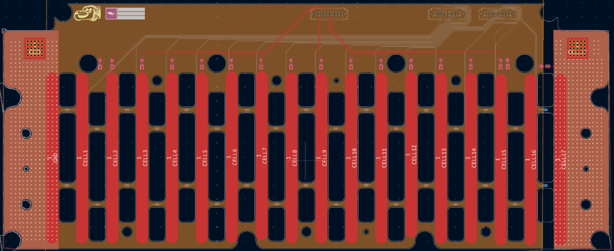
V1 board layout.
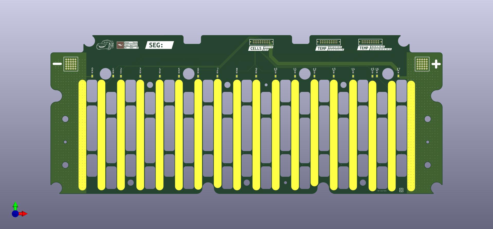
This version fit my first two qualifications of mechanical fit and electrical functionality, but it lacked design quality. The main feedback I received on this design was “more silkscreen!”. Some of my traces were also relatively isolated, which made them prone to EMI—especially worrying since a false temperature spike could shut down our car. In response to the feedback, I consolidated my traces and added informative silkscreen that identified connector numbers, segment numbers, polarity, and parallel cell group numbers.
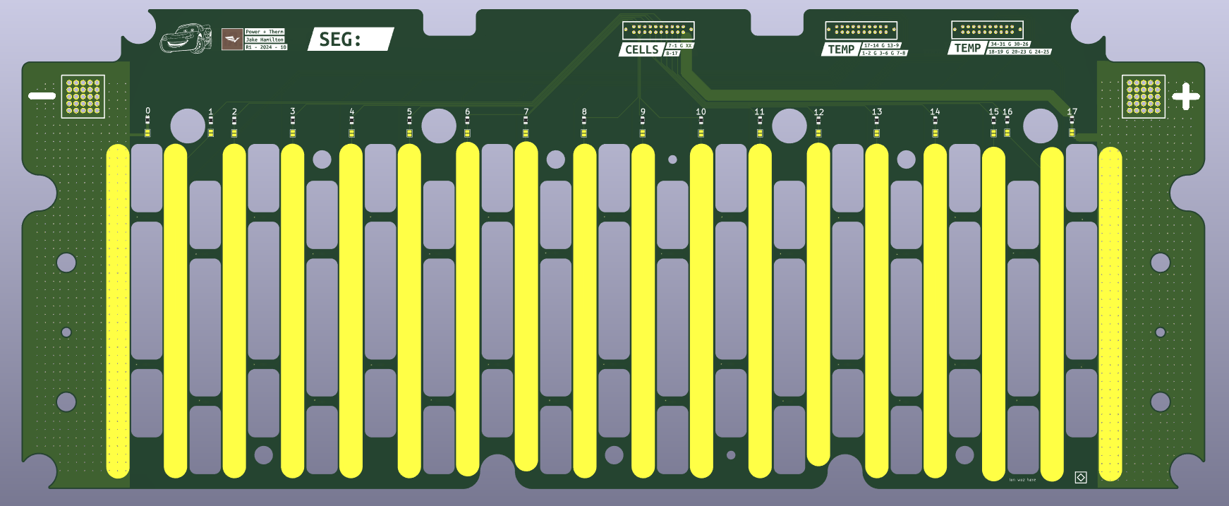
V2 board layout.
Manufacturing and Testing
This board was the final revision and was then sent out for manufacturing. Each project on our electrical team had one owner from start to finish, so after this board came in from JLCPCB, it was my duty to populate, test, and integrate it into the car. I had also never done SMD soldering prior to this project, and it was an incredibly fun learning experience. I fried a couple of LEDs on a test board, but after that, my technique improved and I was able to fully populate eight copies of my board (six for the car, one for testing, one backup).
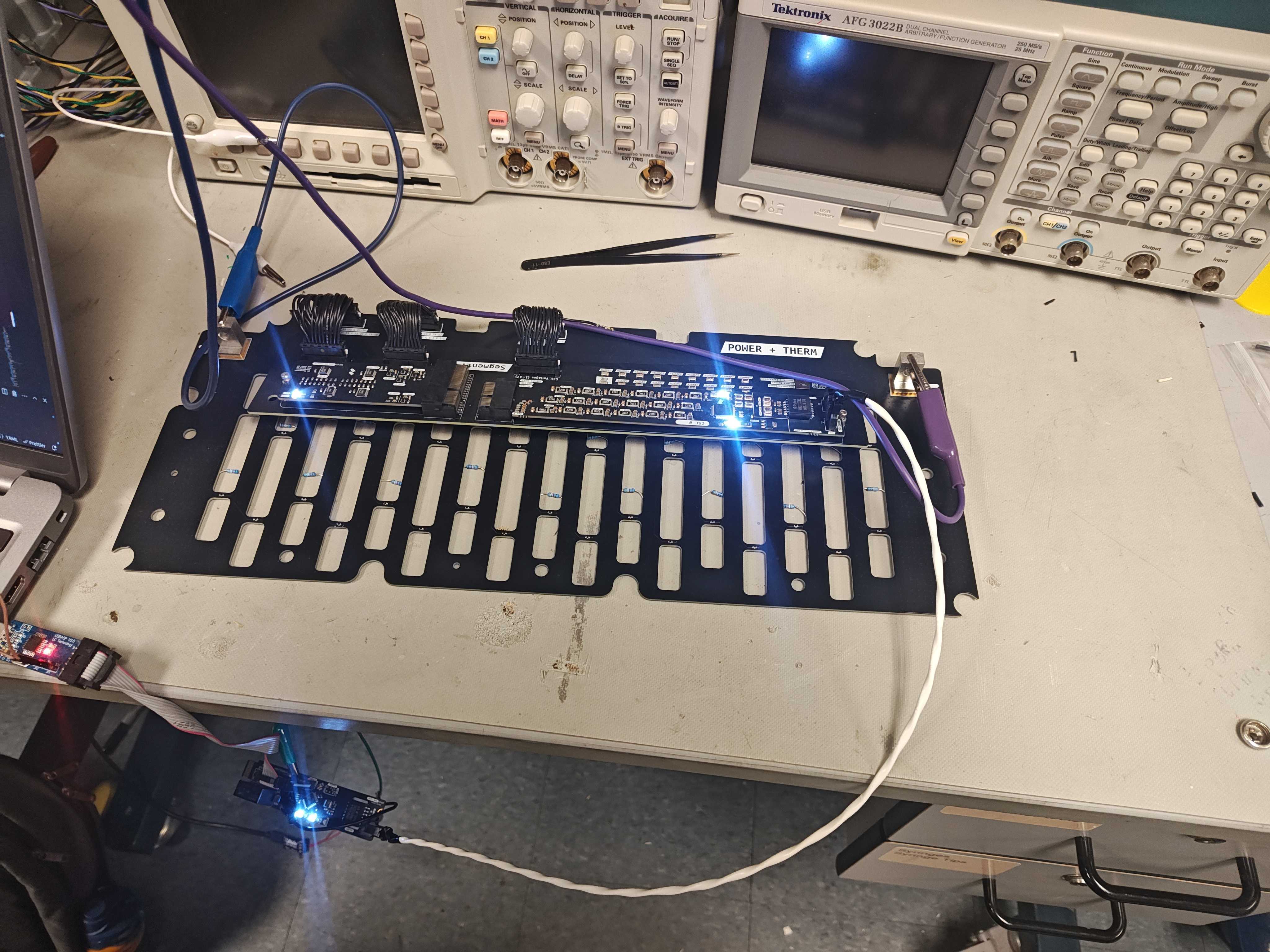
After populating, I tested all of the boards using our BMS test motherboard.
BMS test setup powered by a power supply and resistor divider to simulate cells.
In this process, I found a couple of dead thermistors and was able to replace them quickly. This process of testing boards taught me how to run test procedures and document them in our file system (Coda). On prior projects, I had just kept a mental note of issues, but when working on a team, it was important that others knew the issues I had found for future design cycles.
Reflection and Future Improvements
This project taught me all of my KiCad and PCB design basics, along with more general circuit knowledge, SMD soldering, and testing procedures. It was an incredibly fun project and really helped me fall in love with FSAE. I had an amazing set of mentors who helped me perfect my designs and walked me through the learning process.
If I had to do this board again, I would change the connectors we used, as they sometimes come a bit loose after large jolts to the car, causing a BMS fault and shutting the car down. I would also change the thermistors to be more reliable; right now at room temperature, there is a 2-3 degree Celsius difference between them. This could be corrected with a calibration algorithm, but our team did not have the time to do that this year as we would have needed to get our entire battery to the same exact temperature for multiple temperature points.
Relevant FSAE Rules
EV.6.3.1: All wires and terminals and other conductors used in the Tractive System must be sized for the continuous current they will conduct.
EV.7.3.1: A Battery Management System must monitor the Accumulator(s) Voltage and Temperature.
EV.7.4.1: The BMS must measure the cell voltage of each cell.
EV.7.4.3: All voltage sense wires to the BMS must have overcurrent protection or meet requirements for no overcurrent protection.
EV.7.4.4: Overcurrent protection must occur in the conductor, wire, or PCB trace directly connected to the cell tab.
EV.7.5.1: The BMS must measure the temperatures of critical points of the Accumulator.
EV.7.5.3: Cell temperatures must be measured at the negative terminal of the respective cell.
EV.7.5.4: The temperature sensor used must be in direct contact with the negative terminal or the negative terminal busbar less than 10 mm away from the connection.
EV.7.5.5: For lithium-based cells, the temperature of a minimum of 20% of the cells must be monitored by the BMS, and they must be equally distributed.
EV.7.5.7: Temperature sensors must have appropriate electrical isolation.
project Management (ongoing)
The trials and tribulations of running an FSAE team.
Overview
Throttle Firmware
Writing throttle logic and fault handling.
Overview
In accordance with FSAE rules, each car needs to have a Brake Speed Plausability Device (BSPD). Among many other functions like calculating throttle travel and brake pressure it also:
EV.4.7.1 Must monitor for the two conditions:
• The mechanical brakes are engaged EV.4.6, T.3.2.4
• The APPS signals more than 25% Pedal Travel EV.4.5
EV.4.7.2 If the two conditions in EV.4.7.1 occur at the same time:
a. Power to the Motor(s) must be immediately and completely shut down
b. The Motor shut down must stay active until the APPS signals less than 5% Pedal Travel,
with or without brake operation
The team must be able to demonstrate these actions at Technical Inspection
Our previous code (pasted at the bottom) had an error where the throttle position was detached from reality and the 25% throtte + brake fault would not latch correctly. After triggering the fault, anytime the throttle then went below 25% the fault would un-latch, instead of unlatching at 5% like it was supposed to. To fix this code I needed to calibrate the throttle and re-think the fault latching logic.
Throttle Calibration
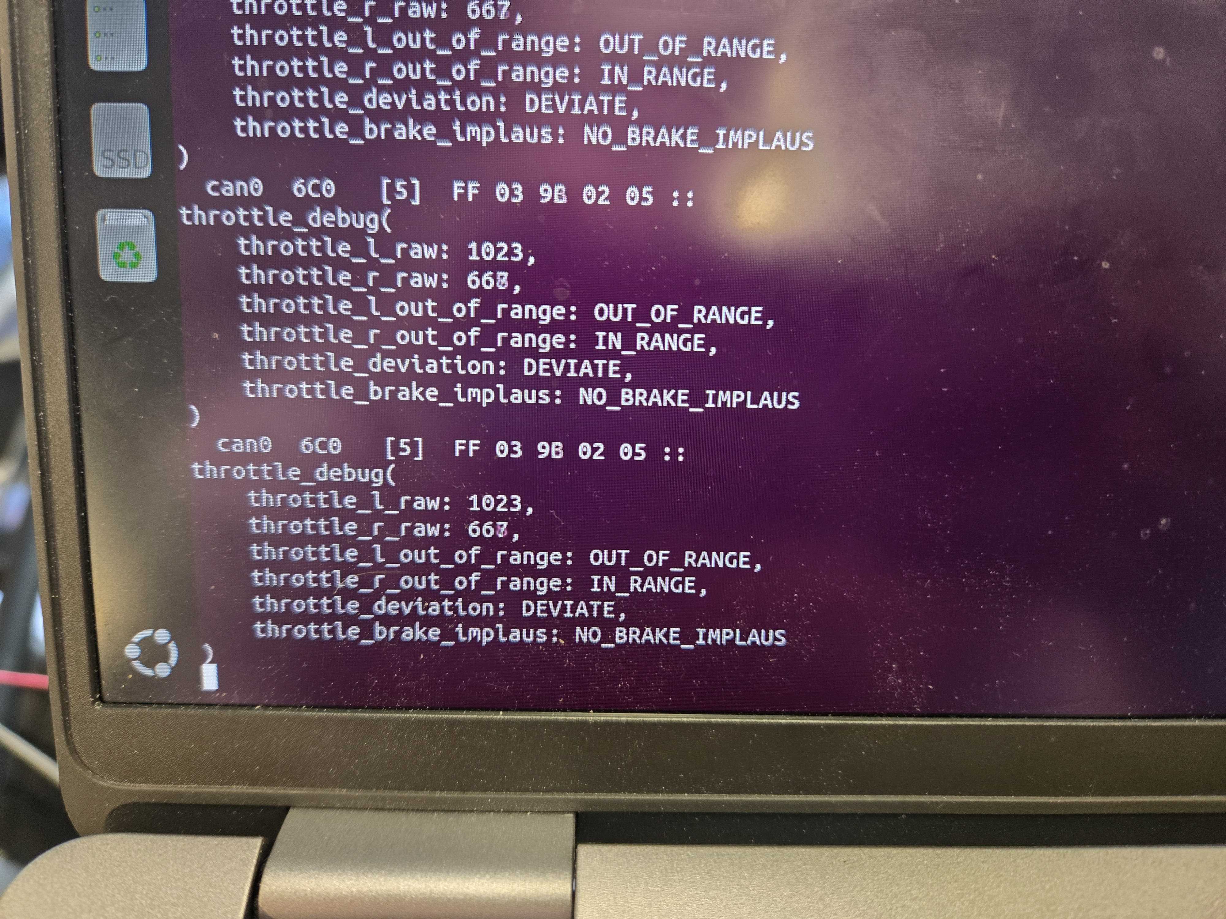
For quick background the throttle is comprised of two different linear potentiometers that are a part of two different voltage dividers, one with a 1kOhm resistor and the other with a 10kOhm resistor. The throttle signal is two different voltages that change as the linear pots travel with the throttle. Since the pots and throttle travel are linear, all I needed to calibrate the throttle was the end voltage and the start voltage. To find these values I used a .dbc file that outputted the raw ADC value of the throttle in real time to the terminal.
Terminal output with throttle at full.
I recorded the max and min values and then I added them to the throttle config file for the firmware.
Each line starts with a ‘#’ that was removed for formatting purposes.
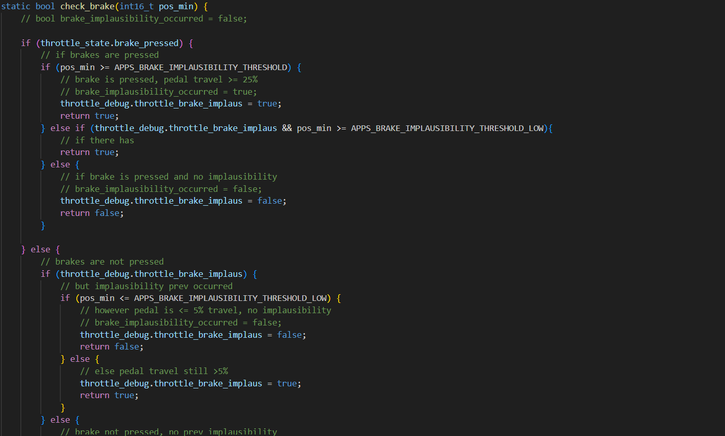
New Brake Fault Code
staticboolcheck_brake(int16_tpos_min){// bool brake_implausibility_occurred = false;if(throttle_state.brake_pressed){// if brakes are pressedif(pos_min>=APPS_BRAKE_IMPLAUSIBILITY_THRESHOLD){// brake is pressed, pedal travel >= 25%// brake_implausibility_occurred = true;throttle_debug.throttle_brake_implaus=true;returntrue;}elseif(throttle_debug.throttle_brake_implaus&&pos_min>=APPS_BRAKE_IMPLAUSIBILITY_THRESHOLD_LOW){// if there has returntrue;}else{// if brake is pressed and no implausibility// brake_implausibility_occurred = false;throttle_debug.throttle_brake_implaus=false;returnfalse;}}else{// brakes are not pressedif(throttle_debug.throttle_brake_implaus){// but implausibility prev occurredif(pos_min<=APPS_BRAKE_IMPLAUSIBILITY_THRESHOLD_LOW){// however pedal is <= 5% travel, no implausibility// brake_implausibility_occurred = false;throttle_debug.throttle_brake_implaus=false;returnfalse;}else{// else pedal travel still >5%throttle_debug.throttle_brake_implaus=true;returntrue;}}else{// brake not pressed, no prev implausibilitythrottle_debug.throttle_brake_implaus=false;returnfalse;}}}
Old Brake Fault Code
staticboolcheck_brake(int1hundred_tpos_min){staticboolbrake_implausibility_occurred=false;if(throttle_state.brake_pressed){// if brakes are pressedif(pos_min>=APPS_BRAKE_IMPLAUSIBILITY_THRESHOLD){// brake is pressed, pedal travel >= 25%brake_implausibility_occurred=true;throttle.throttle_status=THROTTLE_BRAKE_PRESSED;throttle_debug.throttle_brake_implaus=true;returntrue;}else{// brake is pressed, pedal travel < 25%// no implausibilitythrottle_debug.throttle_brake_implaus=false;}if(brake_implausibility_occurred){// if brake is pressed & implausibility prev occurredif(pos_min<=APPS_BRAKE_IMPLAUSIBILITY_THRESHOLD_LOW){// and pedal travel <= 5%brake_implausibility_occurred=false;throttle.throttle_status=THROTTLE_RUN;throttle_debug.throttle_brake_implaus=false;returnfalse;}else{// implausibility prev occurred, pedal travel > 5%throttle_debug.throttle_brake_implaus=true;throttle.throttle_status=THROTTLE_BRAKE_PRESSED;returntrue;}}else{// no implausibility prev occurred then still no implausibilitythrottle.throttle_status=THROTTLE_RUN;throttle_debug.throttle_brake_implaus=false;returnfalse;}}else{// brakes are not pressedif(brake_implausibility_occurred){if(pos_min<=APPS_BRAKE_IMPLAUSIBILITY_THRESHOLD_LOW){// however pedal is <= 5% travel, no implausibilitybrake_implausibility_occurred=false;throttle_debug.throttle_brake_implaus=false;throttle.throttle_status=THROTTLE_RUN;returnfalse;}else{// else pedal travel still >5%throttle.throttle_status=THROTTLE_BRAKE_PRESSED;throttle_debug.throttle_brake_implaus=true;returntrue;}}else{// brake not pressed, no prev implausibilitythrottle.throttle_status=THROTTLE_RUN;throttle_debug.throttle_brake_implaus=false;returnfalse;}}}
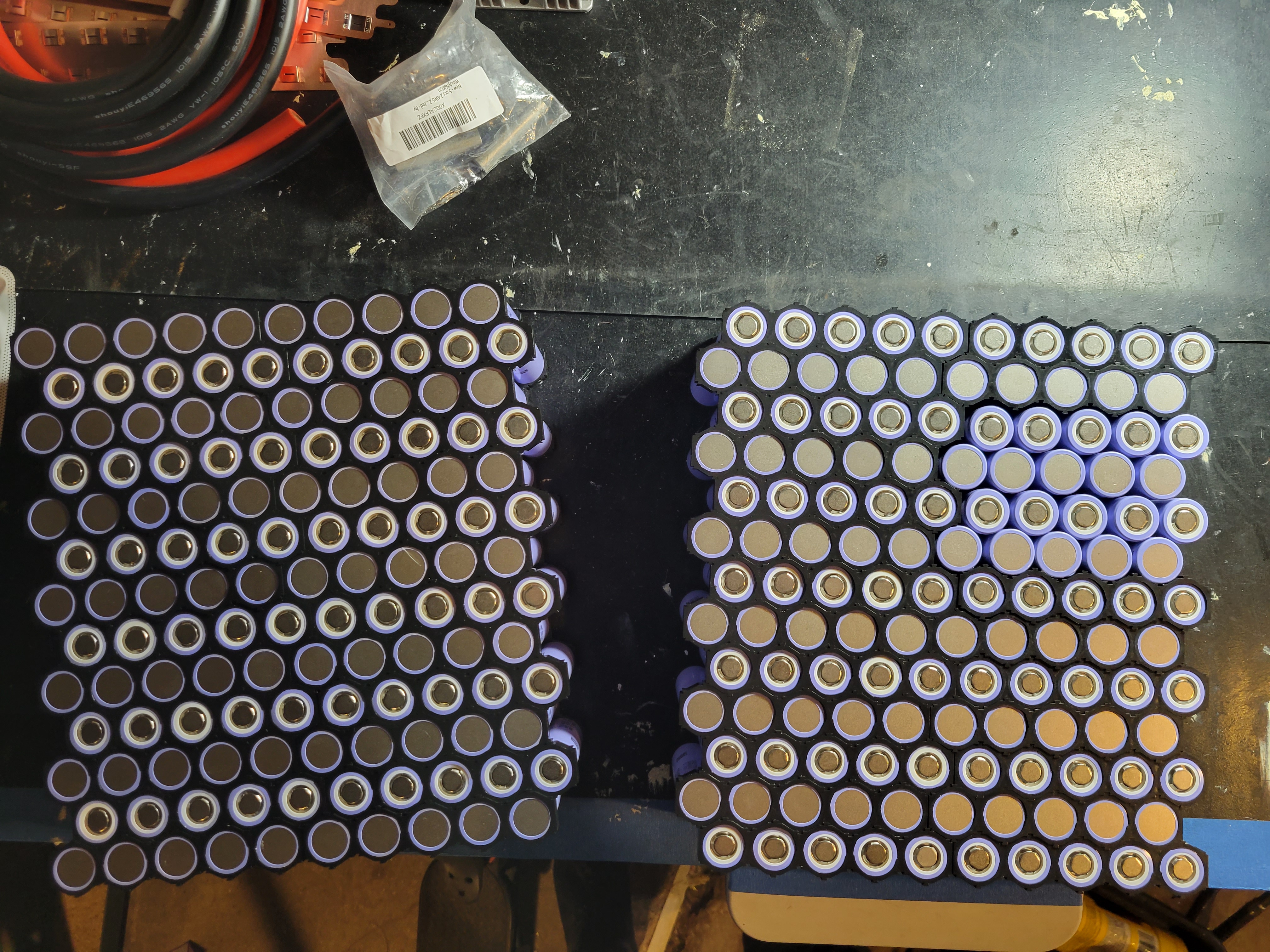
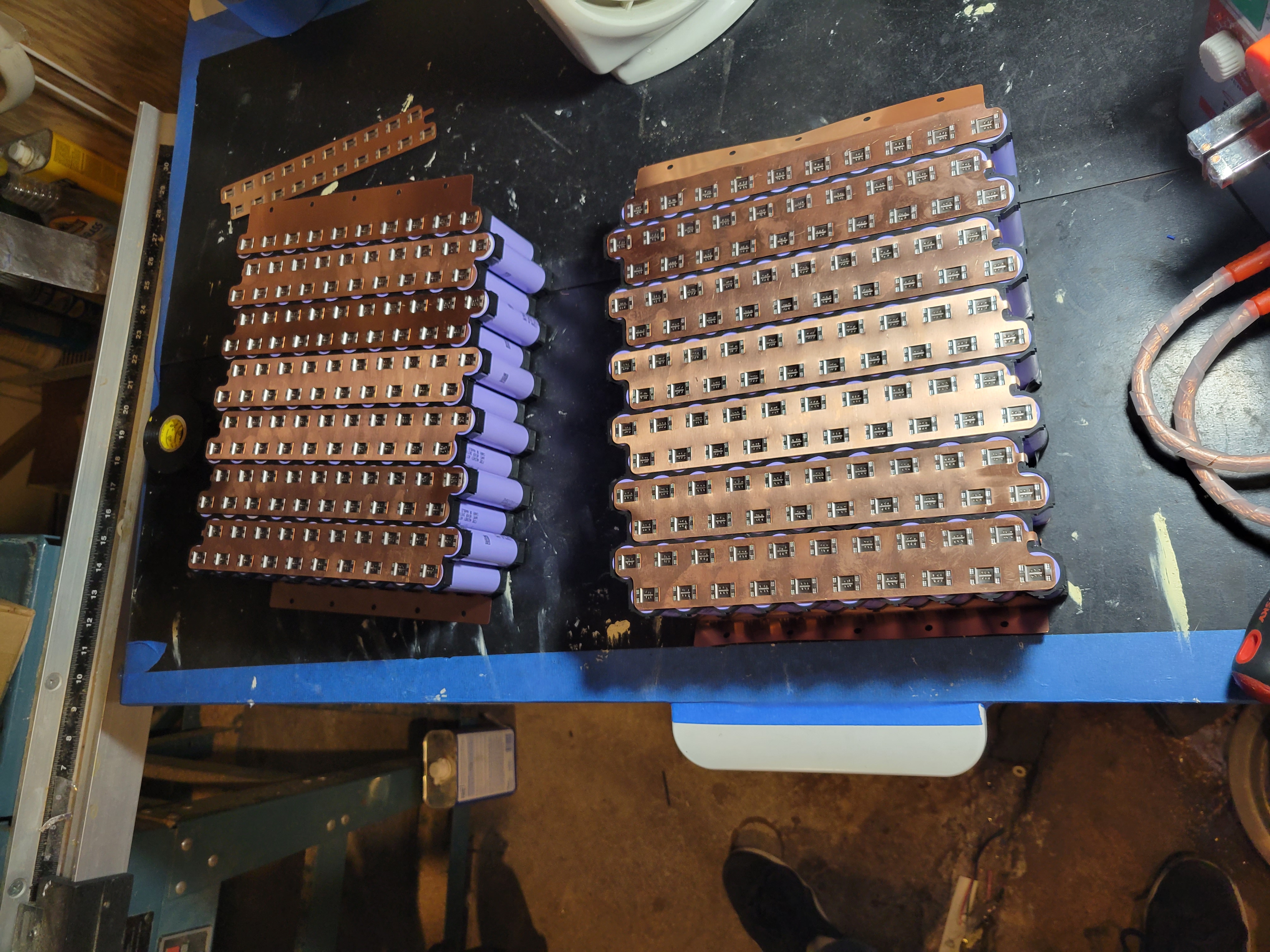 The cells in holders (left) and with the bus bars spot-welded on (right).
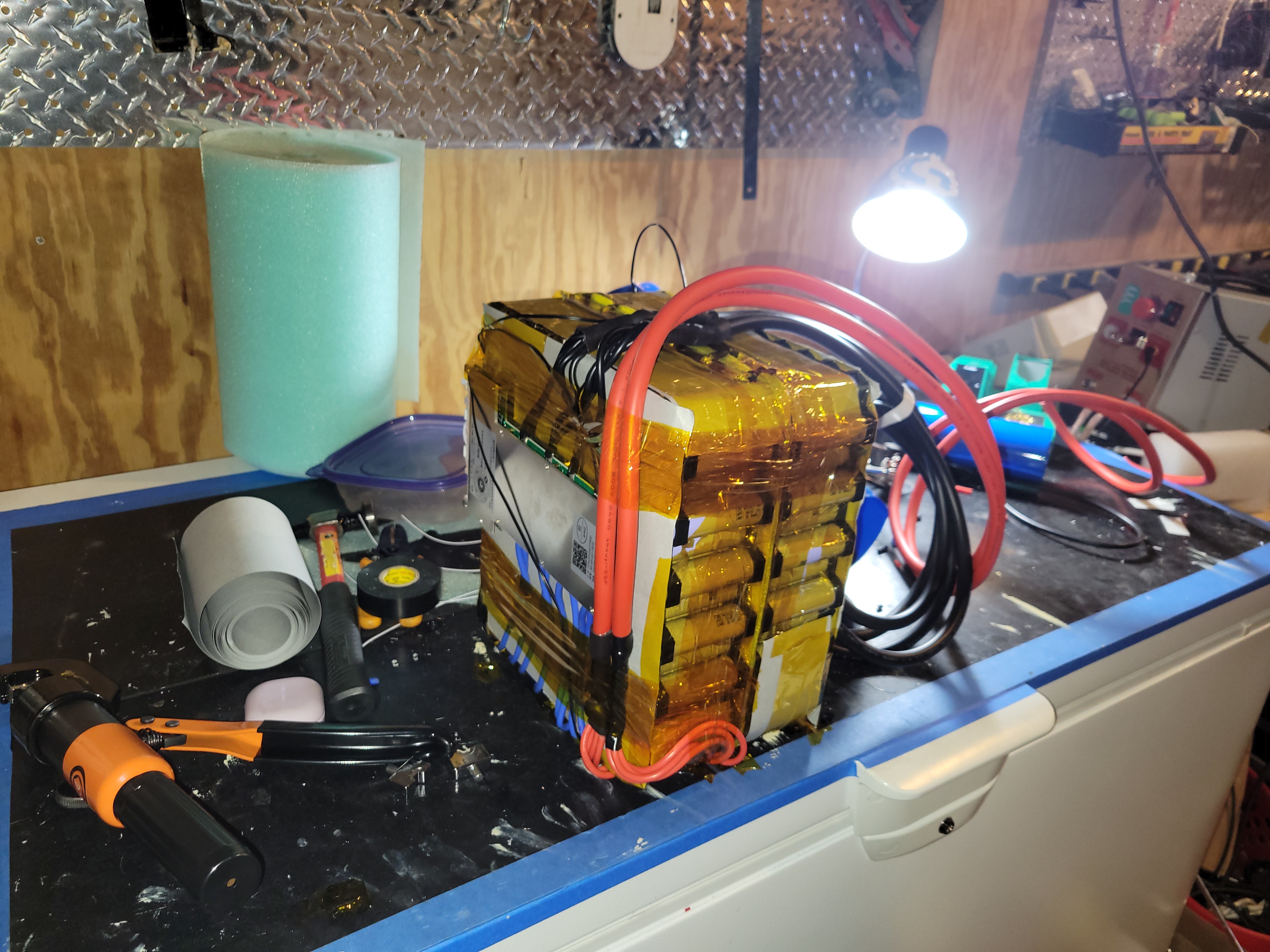
 The battery almost finished (left) and fully wrapped (right).
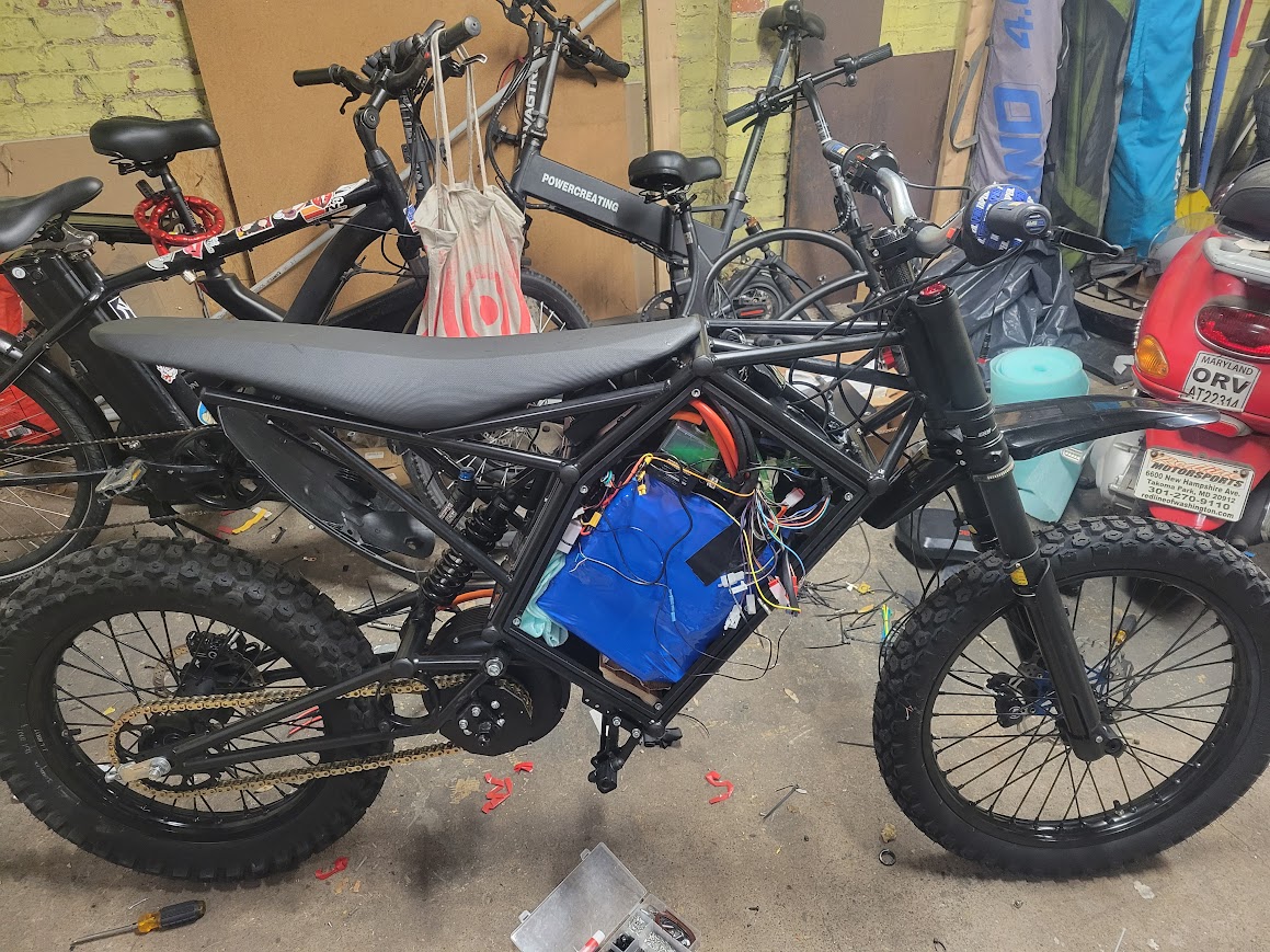
 A selection of suspension parts, the battery, and the motor for the bike.
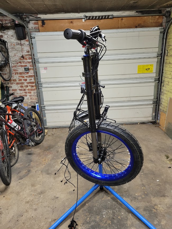
 The segments of the battery separately (left) and then soldered together (right).
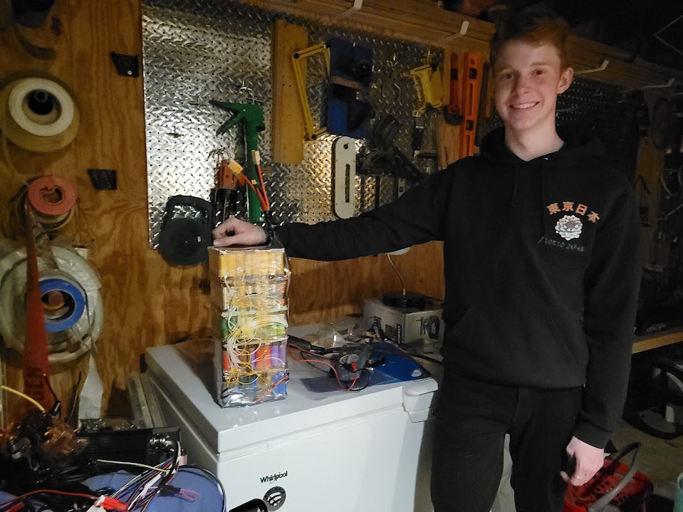
 Spline adapter v1 (left) and spline adapter v4 (right).
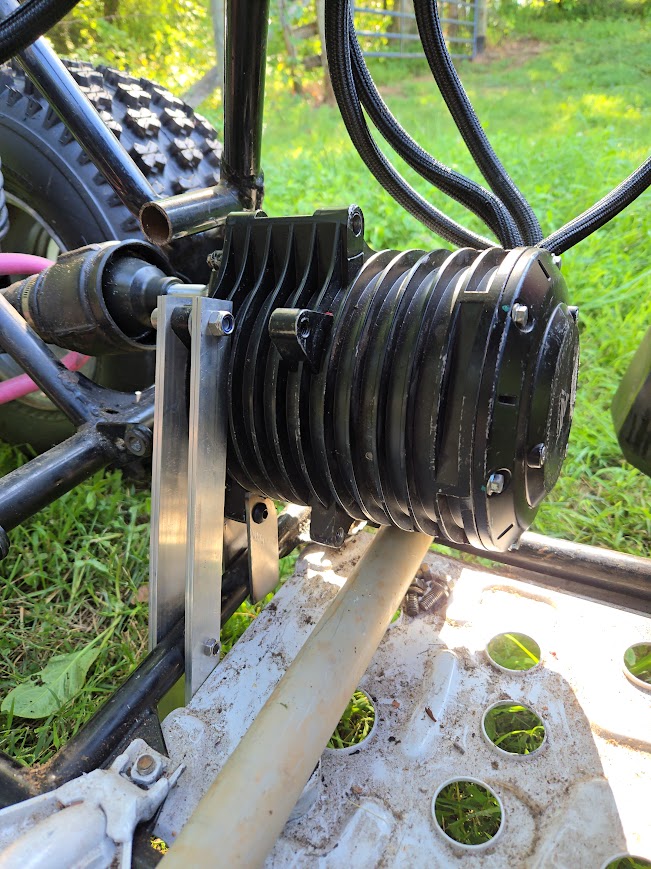
 Terminal output with throttle at full.